Search for articles or browse our knowledge portal by topic.
Clear Zone Overview
Most of Kentucky’s roadway fatalities result from roadway departure collisions. Kentucky’s Strategic Highway Safety Plan notes that providing adequate clear zones can facilitate the safe recovery of errant vehicles and help prevent roadway departure collisions. Implementing the clear zone concept improves safety by creating a more forgiving roadside.
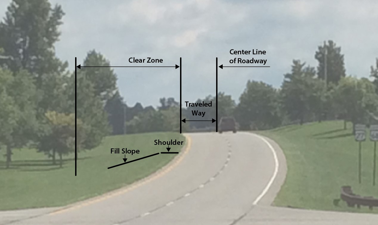
The Roadside Design Guide (RDG) defines the clear zone as the unobstructed, traversable area provided beyond the edge of the through traveled way for the recovery of errant vehicles. The clear zone includes shoulders, bike lanes, and auxiliary lanes, except those auxiliary lanes that function like through lanes. The RDG provides guidance for applying the clear zone concept in rural and urban settings. Recommended clear zone distances vary based on traffic volumes, speeds, and roadside geometry. These distances are neither absolute nor precise. In some cases, it may be reasonable to leave a fixed object or have non-traversable terrain within the clear zone. Use engineering judgement when establishing a clear zone. Clear zones should be as wide as practical given the safety, contextual, environmental, and economic constraints.
Listed below are six roadway design strategies for providing an unobstructed clear zone (in order of preference):
- Remove the obstacle.
- Redesign the obstacle for safe traversal.
- Relocate the obstacle further from the roadway (or move the roadway further from obstacle).
- Reduce obstacle severity (make it breakaway).
- Shield the obstacle with a traffic barrier or a crash cushion.
- Delineate the obstacle if the above alternatives are not feasible.
| Table 2-1 The RDG's Suggested Clear Zone Distances from Edge of Through Traveled Lane | |||||||||||
|---|---|---|---|---|---|---|---|---|---|---|---|
| Design Speed (mph) | Design ADT | Foreslopes | Backslopes | ||||||||
| 1V:6H or flatter | 1V:5H to 1V:4H | 1V:3H | 1V:3H | 1V:5H to 1V:4H | 1V:6H or flatter | ||||||
| < 40 |
|
7-10 10-12 12-14 14-16 |
7-10 10-12 14-16 16-18 |
See Note b |
7-10 10-12 12-14 14-16 |
7-10 10-12 12-14 14-16 |
7-10 10-12 12-14 14-16 |
||||
| 45 - 50 |
|
10-12 14-16 16-18 20-22 |
12-14 16-20 20-26 24-28 |
See Note b |
8-10 10-12 12-14 14-16 |
8-10 12-14 14-16 18-20 |
10-12 14-16 16-18 20-22 |
||||
| 55 |
|
12-14 16-18 20-22 22-24 |
14 - 18 20 - 24 24 - 30 26 - 32a |
See Note b |
8-10 10-12 14-16 16-18 |
10-12 14-16 16-18 20-22 |
10-12 16-18 20-22 22-24 |
||||
| 60 |
|
16-18 20-24 26-30 30-32a |
20 -24 26-32a 32-40a 36-44a |
See Note b |
10-12 12-14 14-18 20-22 |
12-14 16-18 18-22 24-26 |
14-16 20-22 24-26 26-28 |
||||
| 65 - 70d |
|
18-20 24-26 28-32a 30-34a |
20 -26 28-36a 34-42a 38-46a |
See Note b |
10-12 12-16 16-20 22-24 |
14-16 18-20 22-24 26-30 |
14-16 20-22 26-28 28-30 |
||||
Source: RDG July 2015 Errata (Table 3-1)
Table Key Notes:
a) When a site-specific investigation indicates a high probability of continuing crashes or when such occurrences are indicated by crash history, the designer may provide clear-zone distances greater than the clear zone shown in Table 2-1. Clear zones may be limited to 30 feet for practicality and to provide a consistent roadway template if previous experience with similar projects or designs indicates satisfactory performance.
b) Because recovery is less likely on the unshielded, traversable 1V:3H fill slopes, fixed objects should not be present in the vicinity of the toe of these slopes. Recovery of high-speed vehicles that encroach beyond the edge of the shoulder may be expected to occur beyond the toe of slope. Determination of the width of the recovery area at the toe of slope should consider right of way availability, environmental concerns, economic factors, safety needs, and crash histories. Also, the distance between the edge of the through traveled lane and the beginning of the 1V:3H slope should influence the recovery area provided at the toe of slope. While the application may be limited by several factors, the foreslope parameters that may enter into determining a maximum desirable recovery area are illustrated in Figure 4-1. A 10-foot recovery area at the toe of slope should be provided for all traversable, non-recoverable fill slopes.
c) For roadways with low volumes, it may not be practical to apply even the minimum values found in Table 2-1. Refer to RDG Chapter 12 for additional considerations for low-volume roadways and RDG Chapter 10 for additional guidance for urban applications.
d) When design speeds are greater than the values provided, the designer may provide clear-zone distances greater than those shown in Table 2-1.
The RDG provides adjustment factors for horizontal curvature that may be applied to distances in Table 2-1. Table 2-2 reproduces these adjustment factors. Figure 2-1 depicts the base clear zone and adjusted clear zone of a horizontal curve.
| Table 2-2 The RDG’s Horizontal Curve Adjustment Factor for Clear Zones | ||||||
|---|---|---|---|---|---|---|
| Radius (ft) | Design Speed (mph) | |||||
| 40 | 45 | 50 | 55 | 65 | 70 | |
| 2950 | 1.1 | 1.1 | 1.1 | 1.2 | 1.2 | 1.2 |
| 2300 | 1.1 | 1.1 | 1.2 | 1.2 | 1.2 | 1.3 |
| 1970 | 1.1 | 1.2 | 1.2 | 1.2 | 1.3 | 1.4 |
| 1640 | 1.1 | 1.2 | 1.2 | 1.3 | 1.3 | 1.4 |
| 1475 | 1.2 | 1.2 | 1.3 | 1.3 | 1.4 | 1.5 |
| 1315 | 1.2 | 1.2 | 1.3 | 1.3 | 1.4 | - |
| 1150 | 1.2 | 1.2 | 1.3 | 1.4 | 1.5 | - |
| 985 | 1.2 | 1.3 | 1.4 | 1.5 | 1.5 | - |
| 820 | 1.3 | 1.3 | 1.4 | 1.5 | - | - |
| 660 | 1.3 | 1.4 | 1.5 | - | - | - |
| 495 | 1.4 | 1.5 | - | - | - | - |
| 330 | 1.5 | - | - | - | - | - |
CZC=(LC)*(KCZ)
where:
CZC = Clear zone on outside of curvature, feet
LC = Clear zone distance, feet (see Table 2-1)
KCZ = Curve correction factor
Note: The clear-zone correction factor is applied to the outside of curves only. Corrections are typically made only to curves less than 2,950-ft radius.
Figure 2-1: Adjusted Clear Zone for Horizontal Curves
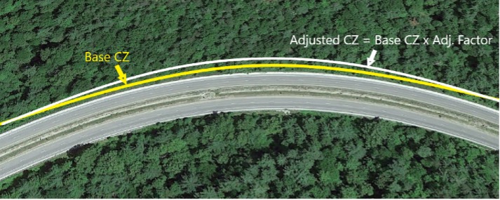
Photo Source: Google Earth
AASHTO’s Guidelines for Geometric Design of Low-Volume Roads (2nd Edition) includes guidance for local roads and minor collector roads with design average daily traffic volumes ≤ 2,000 vehicles per day (vpd). It is generally not cost-effective to establish a clear zone on low-volume roads, however, it may be appropriate where minimum radius of curvature is not provided, or the cost of establishment is minimal. For roadways with design volumes ≤ 400 vpd, AASHTO makes the following recommendations:
- If a clear zone can be established at low cost and with minimal social or environmental impacts, consider providing 6 ft of recovery. Narrower widths can be used if constraints make this impractical.
- Consider site-specific conditions (e.g., horizontal curves with a history of crashes) when making a decision. Adjustable clear zone widths may be appropriate.
- Consider crash history, future growth, and the presence of vehicles with wide loads (e.g. farm equipment).
For local roads and minor collector roads with design traffic volumes between 400 and 2,000 vpd, AASHTO recommends a clear zone width of 7 to 10 ft. See Section 4.7 of AASHTO’s Guidelines for Geometric Design of Low Volume Roads (2nd Edition) for more information. For rural roads with design volumes < 2,000 vpd classified as arterials or major collectors, use clear zone values in Table 2-1.
For urban areas the distances in Table 2-1 may be impractical. See the article Enhanced Lateral Offsets in Urban Environments and RDG Chapter 10 for more information on establishing clear zones in urban areas.
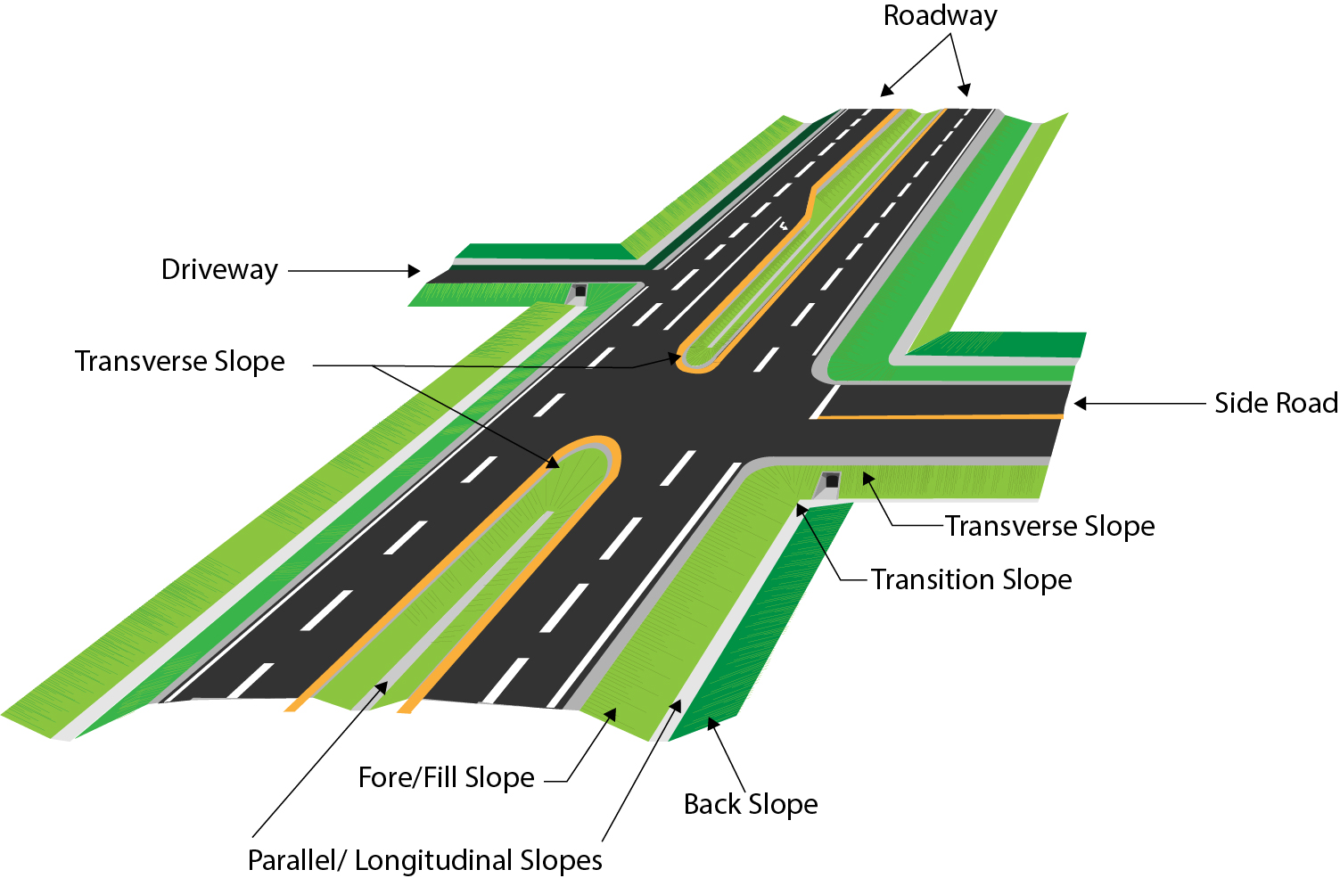
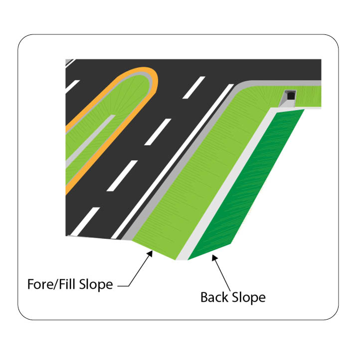
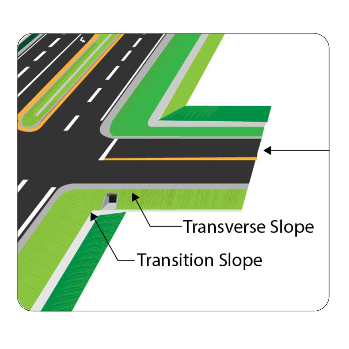
Roadside geometry may include a foreslope, backslope, transverse slope, and drainage channel (Figure 3.1). These features influence the lateral encroachment and trajectory of errant vehicles that depart the roadway.
Figure 3-1: Roadway Geometry Features
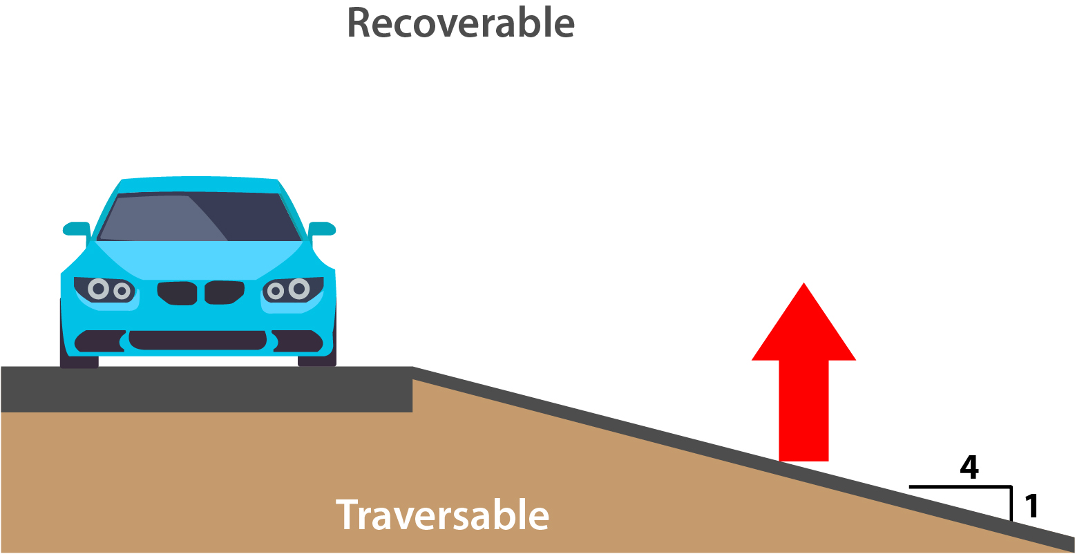
Slopes are classified as recoverable, non-recoverable, or critical.
- Recoverable slopes are slopes on which a motorist may, to a greater or lesser extent, retain or regain control of a vehicle. Slopes 4:1 and flatter are generally considered recoverable. See Figure 3.2.
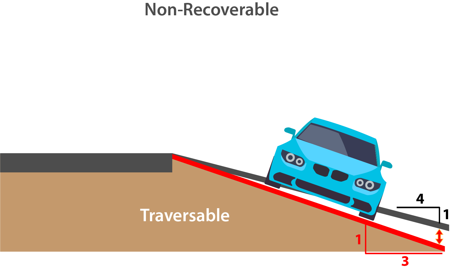
- A critical slope is a slope on which a vehicle is likely to overturn. Slopes steeper than 3:1 are generally considered critical.
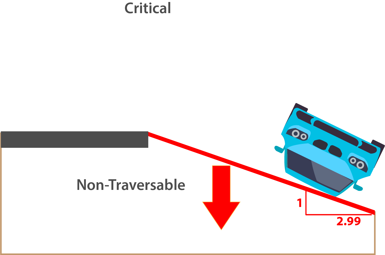
3.1 Foreslopes
Foreslopes, or fill slopes, are parallel to the flow of traffic and are the front or negative slopes that usually hinge from the roadway’s shoulder. Foreslopes may be recoverable, non-recoverable, or critical. Foreslopes steeper than 4:1 are not desirable because their use severely limits the choice of traversable backslope configurations.
3.2 Backslopes
The backslope is a positive slope that extends upward from the base of the foreslope or toe of the ditch. In a roadway cut section the backslope may be traversable depending on its relative smoothness and the presence of fixed obstacles.
3.3 Transverse Slope
Transverse slopes are not parallel to the roadway and are usually created by median crossovers, berms, driveways, or intersecting roadways. They have the potential to be more serious to errant motorists since collisions with transverse slopes would typically be head-on. Transverse slopes of 6:1 or flatter are suggested, particularly for the sections located immediately adjacent to traffic. On high-speed roadways, transverse slopes are often 10:1 or flatter
3.4 Drainage Channels
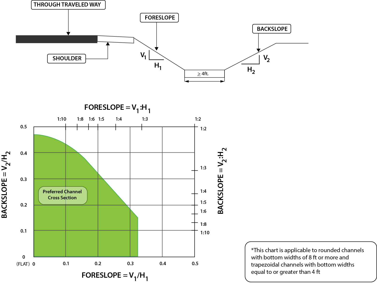
Drainage channels usually parallel the roadway and should be able to accommodate and convey stormwater. Their design, construction, and maintenance need to account for the clear zone. Figures 3-3 and 3-4 present preferred foreslope and backslope values for vee ditch and flat-bottom ditches, respectively. Cross sections categorized as preferable in Figures 3-3 and 3-4 (the shaded regions) are not treated as obstacles because they are traversable.
Figure 3-3: The RDG’s Preferred Cross Sections for Channels with Abrupt Slope Changes
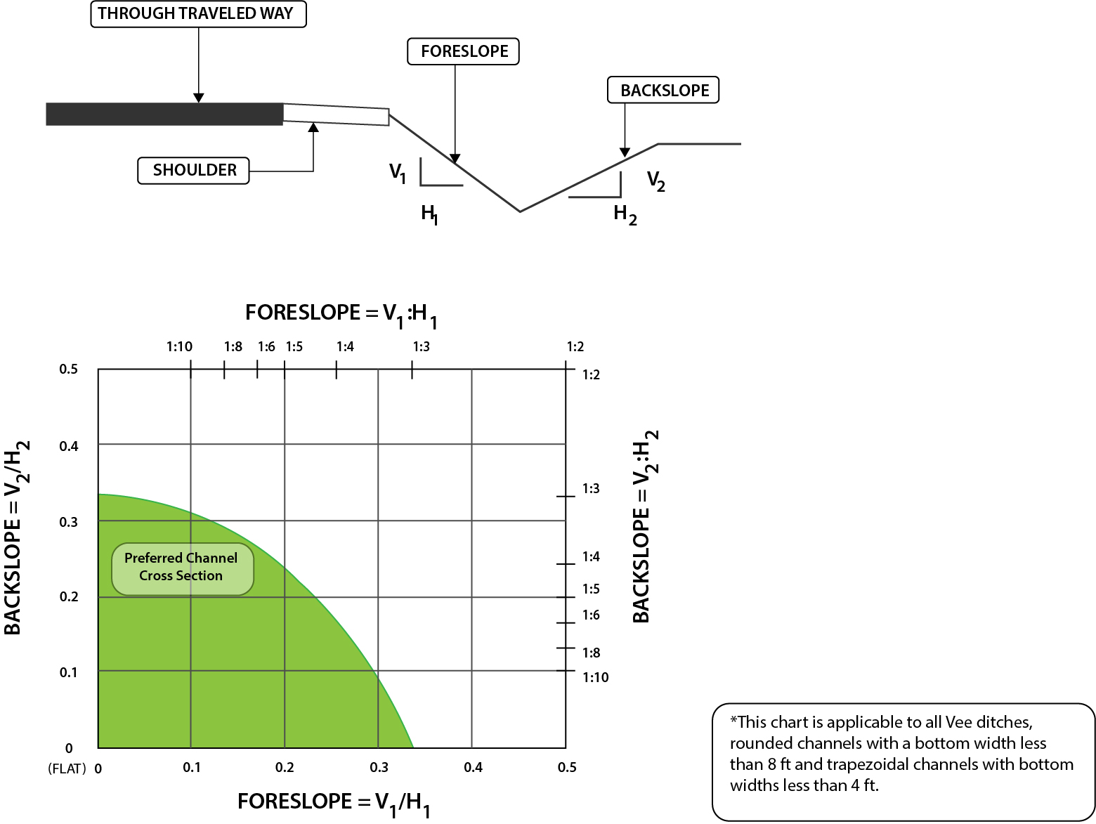
Source: RDG Figure 3-6
Figure 3-4: The RDG’s Preferred Cross Sections for Channels with Gradual Slope Changes
- HD-800 Roadside Design
AASHTO. Roadside Design Guide, Fourth Edition, RSDG-4. American Association of State Highway and Transportation Officials, Washington, DC, 2011.
AASHTO. Guidelines for Geometric Design of Low-Volume Roads, Second Edition. American Association of State Highway and Transportation Officials, Washington, DC, 2019.
Roadside Safety Clear Zone Concepts Knowledge Book:
Access the complete Knowledge Book here: Roadside Safety Knowledge Book (coming soon) and Clear Zone Concepts Knowledge Book
Next Article: Clear Zone Applications
