

Search for articles or browse our knowledge portal by topic.
Surveying Equipment and Methods
Surveying equipment and methods have evolved dramatically since the early 20th century when surveyors relied on measuring chains and/or tapes and compact theodolites, which are used to accurately measure angles in the field. Stereo plotters arrived in the 1930s, giving engineers a way to determine elevations from aerial photographs. Since then, aerial photography has been the method used most often to develop mapping and large-scale surveys.
The late 1940s saw the invention of electronic measuring devices (EDMs), which measure distances between two points by emitting and detecting electromagnetic waves (infrared, laser, or microwave) and determining amount of time it takes for a signal to travel to a reflector and back to the instrument.
Total stations, which combine electronic theodolites and EDMs into one unit, were developed in the 1980s. Data collectors that automated the recording and tabulation of field data were also introduced in this period. These new technologies transformed surveying and remained the primary field data collection surveying method for many years.
With surveyors today having access to multiple advanced survey technologies, and the practice of surveying continues to evolve very rapidly. This article discusses the most common equipment and methods KTYC uses for surveying and mapping functions:
- Traditional total stations and prism
- GPS receivers
- Aerial photography
- Airplanes
- Drones
- Aerial lidar
- Airplanes
- Uncrewed aerial vehicles
- Terrestrial (ground based) lidar
- Mobile lidar
- Automobiles
Data collectors, also called controllers and electronic field books, are handheld computers that record, manage, and calculate survey data obtained directly from many different types of survey instruments, such as total stations, GNSS receivers, drones, etc. Data collectors are used in conjunction with many of the field surveying techniques in the sections that follow. Data collectors organize the field data into file formats that can be imported into downstream applications such as CAD systems, construction applications and GIS systems.
See HD-303.4 Electronic Data Collectors in the Highway Design Manual and CST 615-6 SDR33 Electronic Field Books in the Construction Manual for more information on data collectors.
Total stations combine a digital theodolite, which takes angular measurements, with an EDM for distance measurements. They are used in conjunction with data collectors to gather and process field data.
Total stations are often used in combination with specialized prisms that are attached to survey poles. Total stations emit laser or infrared beams which are reflected from the prism back to the instrument. Distances are determined by measuring the travel time of the beam. Angles are measured by centering the instrument on the survey pole and the prism at a backsight point and rotating instrument to the point being surveyed (foresight).
Some total stations are reflectorless and do not require the use of a prism. These total stations direct the laser or infrared beam at the surface of interest. No prism or pole is needed. Reflectorless total stations are effective when the point being surveyed cannot be occupied (e.g. overhead wire, rock face, etc.)
Traversing
Surveying with total stations will typically involve traversing, which entails measuring lengths and directions (angles) in a series of connected lines between survey points. The resulting geometric shape composed of these points and lines is referred to as a traverse. Traverses serve two primary purposes in land surveying:
- Represent a property boundary line
- Provide a reference framework to locate other survey features
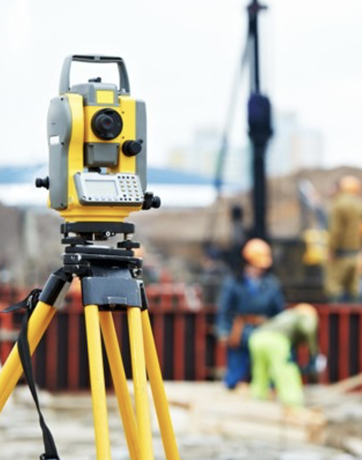
Figure 1 Total Station
There are two basic types of traverses:
- Closed traverse – Traverse where the survey lines open and close on the point of beginning (POB) forming a closed loop.
- Open traverse – Traverse where survey lines begin and end on different points and do not form a closed loop. Typically, the beginning and ending points have known coordinates.
Traverses are typically tied to known control points so that coordinates can be calculated on existing datums and coordinate systems. The example below shows 2 control points with known coordinates and a closed traverse. In this example the traversing procedure starts by occupying Point 2 and performing a backsight observation Point 1. Since the coordinates of these two points are known, our traverse will be tied into a known coordinate system. The instrument is then rotated to make a foresight observation on Point 6, thus measuring angle A and distance 2-6. We now know the bearing of line 2-6 and can proceed surveying around the traverse. Next, with the instrument still set up over Point 2, a backsight observation is performed on Point 6, and the instrument is rotated to make a foresight observation on Point 3, measuring Angle B and distance B-C. The instrument is then moved to Point 3, where a backsight is made on Point 2 and a foresight is made on Point 4. This operation continues in a leapfrog manner around the entire traverse, calculating bearings, distances and coordinates for all points along the way.
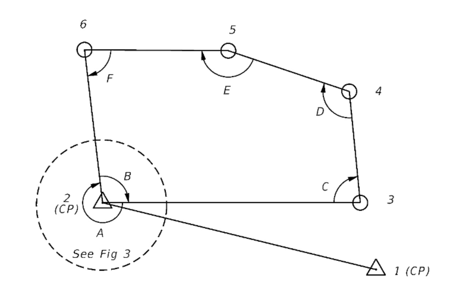
Figure 2 Closed Traverse
After all the traverse measurements are drawn up in office, the resulting geometric shape will not be perfectly closed because of errors in the field. As shown below, the end point will not perfectly coincide with the point of beginning. The distance between these two points is the error of closure and is used to make corrections to the angles and distances measured in the field.
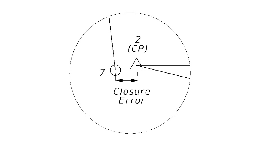
Figure 3 Closure Error
Open traverses work in a similar manner to the procedure above, except that the traverse does not close on itself. Open traverses typically begin and end on known coordinates which allows for similar error calculations and adjustments to the field measurements. Once a traverse has been adjusted for errors it can be used as a reference framework to locate survey features, by occupying the control points and performing foresight observations on each point in the feature.
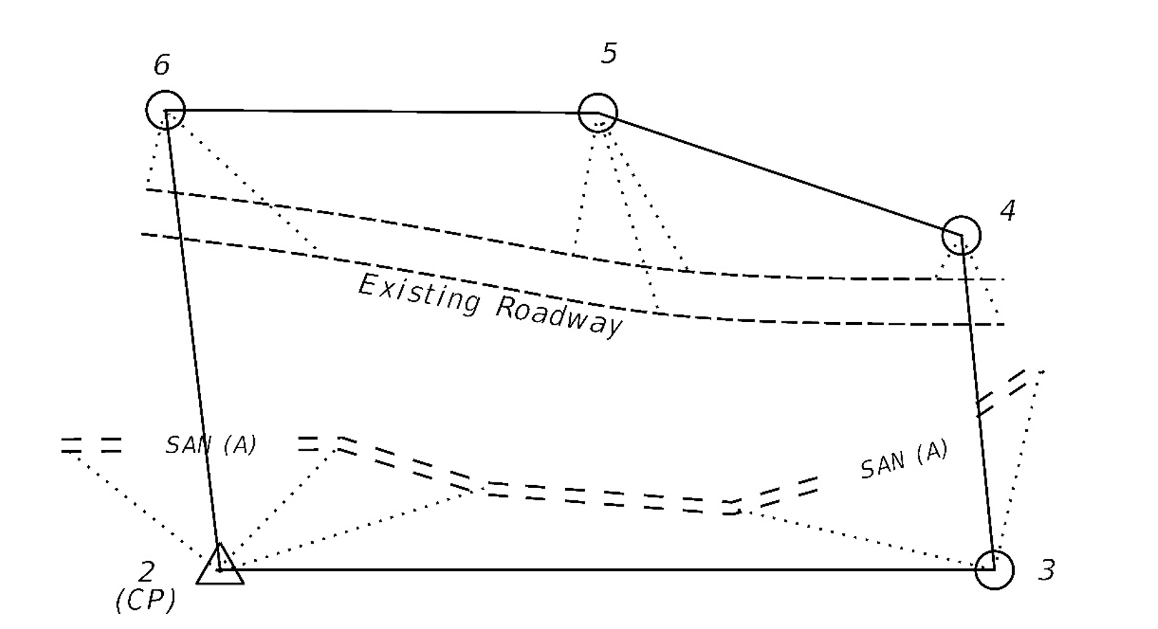
Figure 4 Surveying Features from a Traverse
Differential leveling employs a tripod-mounted level and graduated leveling rod to calculate the difference in elevation between two points. Installed on the level is a telescope that can be leveled to horizontal using a spirit bubble. The optical line of sight forms a horizontal plane, which is at the same elevation as the telescope’s crosshair. The rod is held vertically on a point of known elevation while the level operator reads the rod to determine the difference in elevation between the two points.
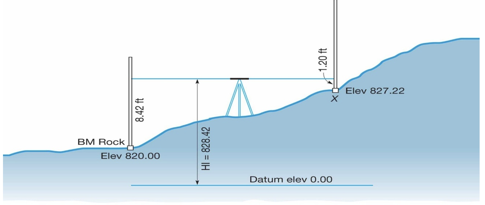
Figure 5 Differential Leveling, (Courtesy of Ben Shinnaberry, University of Kentucky)
GNSS surveying relies on satellite-based signals and known ground reference points to determine precise geographical coordinates. GNSS encompasses multiple satellite networks that provide autonomous, worldwide positioning, navigation, and timing (PNT) services, including GPS (USA), GLONASS (Russia), Galileo (EU), and BeiDou (China). Unlike conventional surveying techniques, GNSS surveying is not bound by constraints such as line-of-sight visibility between survey points. But it does require an unobstructed view of the sky.
Attaining survey-grade measurements via GNSS surveying requires the use of two receivers and the observation of at least four satellites. Two types of receivers are common: base receivers and rover receivers. The base receiver is fixed at a point with known coordinates. The rover receiver is used to occupy survey points and determine their positions; it receives corrections from the base receiver.
5.1 Reference Stations
Reference stations are fixed points whose coordinates must be determined to a high level of accuracy because their purpose is to improve the accuracy of measurements.
A base receiver is set up over the monumented point of the reference station, providing a high-accuracy reference point for the survey. The base receiver also tracks satellite signals to calculate corrections for positioning errors.
Continuously Operating Reference Stations (CORS)
The most commonly used reference stations are the Continuously Operating Reference Stations (CORS) administered by the National Geodetic Survey (NGS). These stations consist of a GNSS antenna and receiver mounted over a fixed monument with known coordinates. A key advantage of CORS receivers is that the base stations are stationed permanently, which means a separate base station does not need to be set up at the survey site.
CORS receivers collect data continuously from GNSS satellites to provide corrections to other GNSS receivers in the area using the station as a reference. The KYCORS website lists CORS in Kentucky.
Existing Monumented Control Points
Any monumented control point can be used as a reference station if it was established in accordance with KYTC guidelines for control. Using existing control points as a reference station involves setting up a stationary base receiver over the known point. The base receiver occupies the point during the entire survey operation. Kentucky Geodetic Reference Network (KGRN) monuments and control points from previous surveys are two examples of points that can be used as GNSS base stations.
See HD-302 Survey Control in the Highway Design Manual and the HKP Article Project Development Surveys for more information on survey control.
5.2 GNSS Surveying Methods
While GNSS surveying methods are developing rapidly, this section focuses on two methods used most often:
- Static
- Real-Time Kinematic (RTK)
Static GNSS Surveying
Static GNSS surveying is the most accurate method and requires the longest observation times. With static GNSS surveying, the base station remains stationary over a reference point. The rover is positioned over an unknown point and kept stationary for an extended period.
CORS receivers are typically used as the base station for static GNSS surveys. While observation times depend on multiple factors, durations are typically between 30 minutes and 2 hours. Data collected via static GNSS surveys must undergo post-processing to correct errors. Because post-processed data are highly accurate, static GNSS surveying is ideal for setting control on projects.
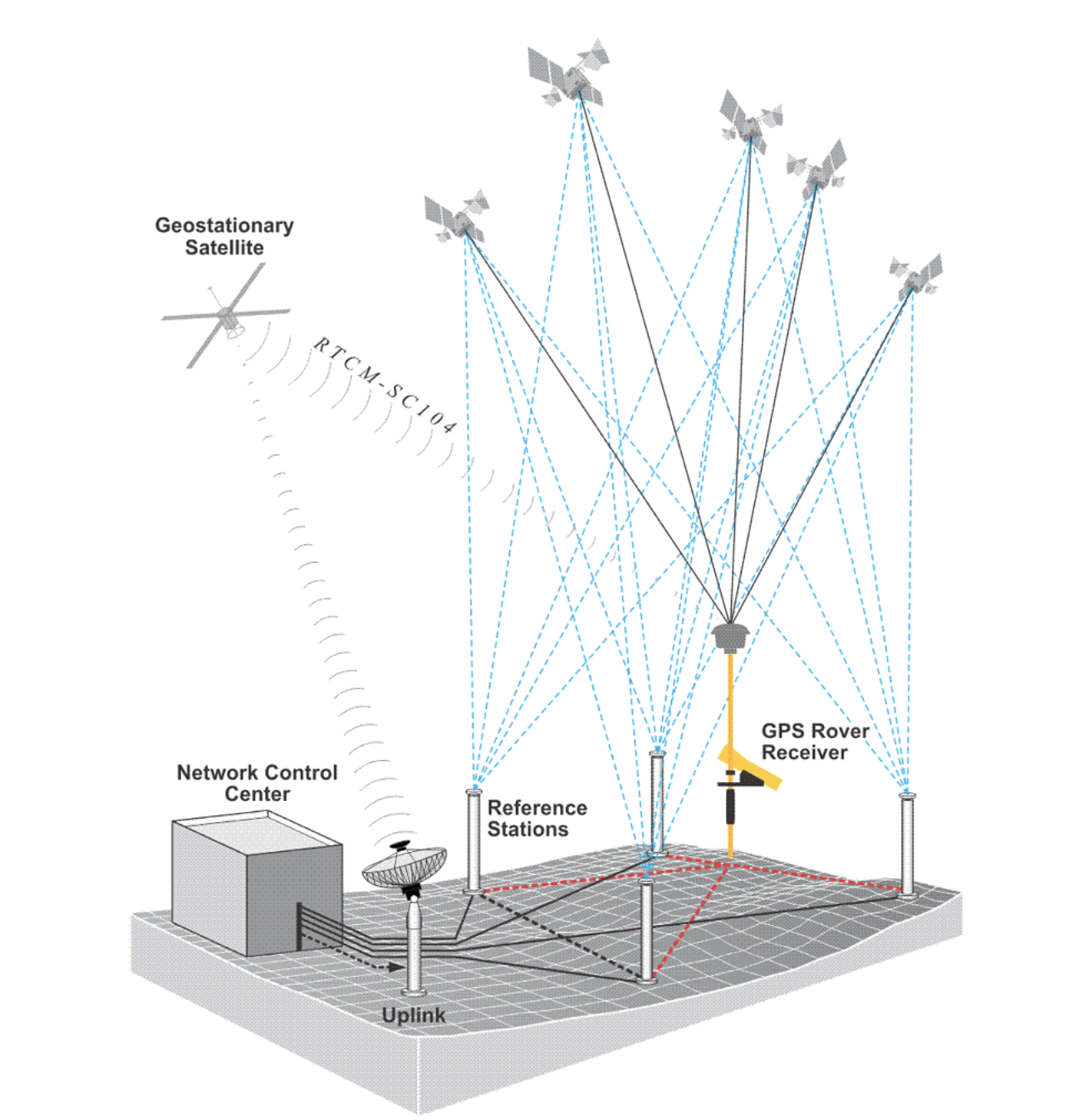
Figure 6 GNSS Surveying (Courtesy of Ben Shinnaberry, University of Kentucky)
Real Time Kinetic (RTK) GNSS Surveying
With RTK GNSS surveys, the base station is set up at a known point and remains stationary. The rover is moved around and occupies unknown points for a short duration (30 seconds or less). The known point used for the base station should be near the project to reduce errors. While it is possible to use a CORS site as the base station for an RTK survey, it could degrade accuracy due to baseline errors. RTK is quickly replacing total station surveying as the method of choice for collecting survey data.
Photogrammetry is the science of creating accurate 3D measurements from 2D photographs by identifying common points across multiple overlapping images. Photogrammetric surveys are an extension of photogrammetry and involve using high-resolution digital photographs to create 3D models and maps. Photos are captured by fixed-wing aircraft or uncrewed aerial vehicles (UAVs) and are post-processed using photogrammetric procedures.
Many statewide sources of aerial photography and photogrammetric data are suitable for planning- levels studies. Project-level photogrammetric data can be obtained via existing survey contracts administered by the Division Highway Design. Historically, aerial photography has been acquired by fixed-wing aircraft through these contracts, however, UAVs are becoming more common as a means to collect aerial data.
KYTC has developed the internal expertise and capabilities to deploy UAVs. Contact the Statewide Survey Coordinators listed on the Survey Drones website for more information on UAV usage and training.
See HD-308 Aerial Mapping in the Highway Design Manual for more information and aerial mapping and the HKP article Survey and Mapping Data (coming soon) for a list of readily available photogrammetric data.
Lidar is a remote sensing technology that uses laser pulses to create 3D maps and models. Lidar systems emit laser pulses that reflect off objects. The system measures the time it takes for pulses to return and uses this information to calculate the distance between the system and the object. Lidar is typically collected by three methods
- Aerial Lidar
- Captured by airplanes or drones
- Terrestrial Lidar
- Stationary Terrestrial Laser Scanning (STLS) – captured by tripod mounted units
- Mobile Terrestrial Laser Scanning (MTLS) aka Mobile LiDAR – captured by units mounted to a vehicle
Each point measured by a Lidar system has x, y, and z coordinates. These points are aggregated into point clouds — 3D representations of an area comprised of individual points. Point clouds are extremely dense and must be post-processed into usable terrain and planimetric data that can then be used to produce mapping and terrain models. (Figure 4).
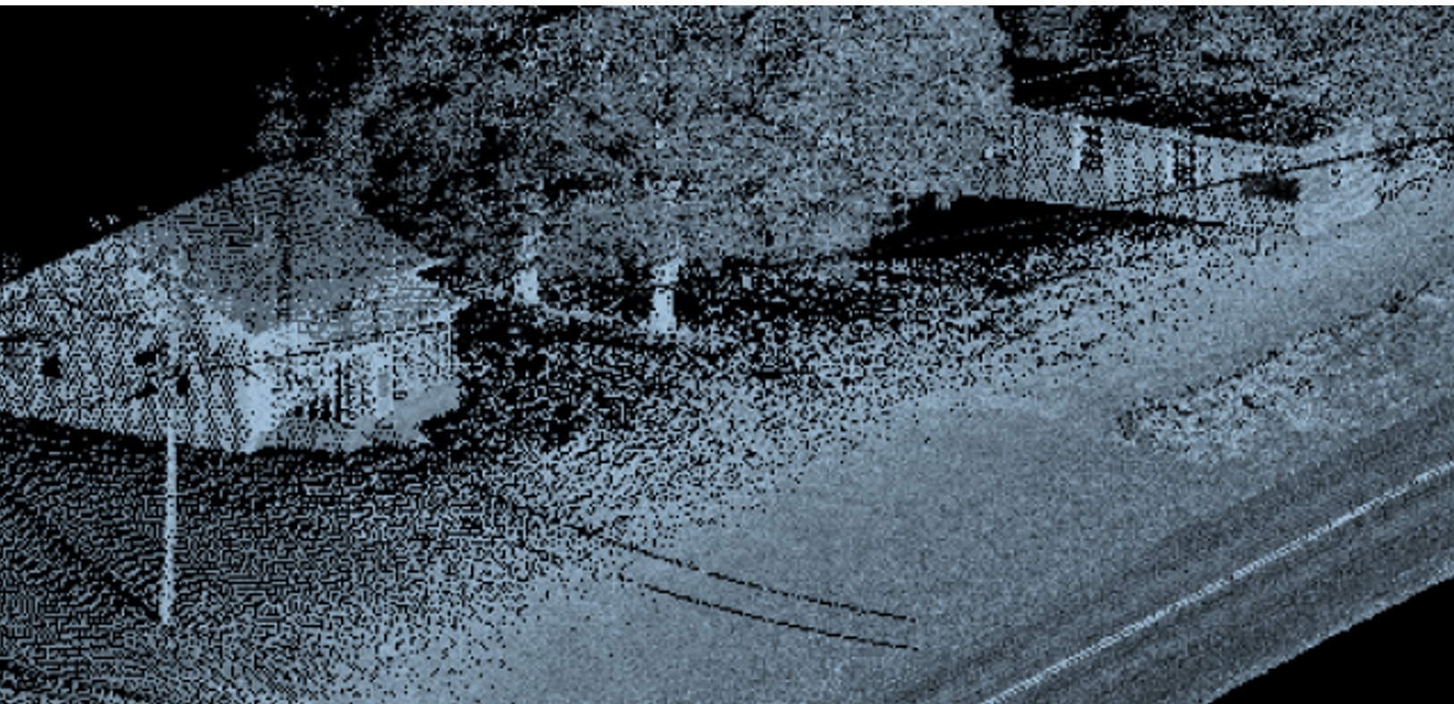
Figure 7 Point Cloud
See HD-308 Aerial Mapping in the Highway Design Manual for more information on aerial Lidar and HD-309 Terrestrial Mapping in the Highway Design Manual for details on terrestrial Lidar. Also, see the HKP article Survey and Mapping Data (coming soon) for a listing available Lidar data.
KYTC Survey Manual (Chapter 300 of Highway Design Manual) (2026). Kentucky Transportation Cabinet.
KYTC Survey Self Help website.