Search for articles or browse our knowledge portal by topic.
Unmanned Aircraft Systems (UAS)
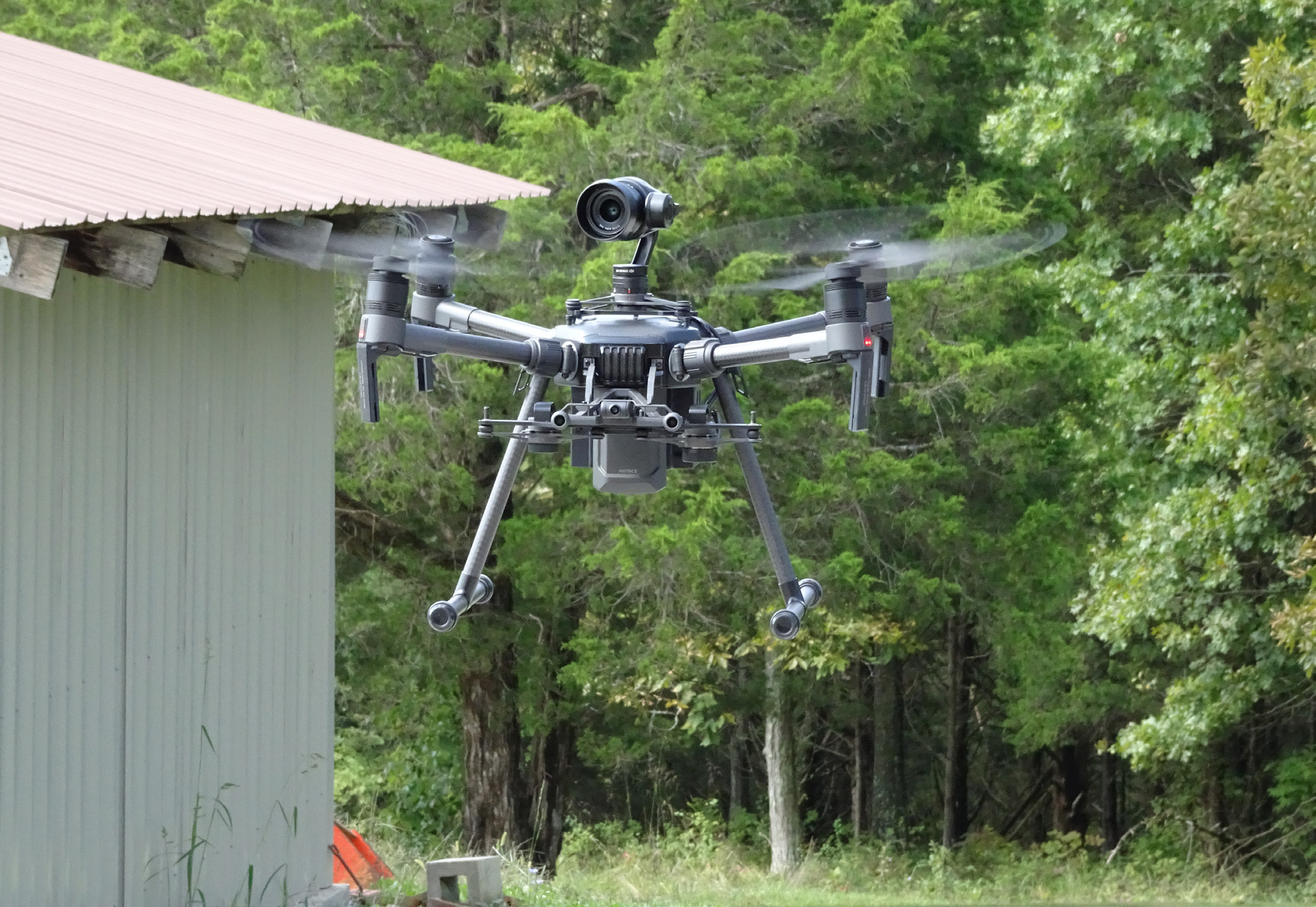
Unmanned aircraft systems (UAS) – which are often referred to as drones – aid highway planning, design, construction, maintenance, and operations. Data products generated by these systems range from the simple (e.g., photo or video) to the complex (e.g., classified point cloud or digital elevation model (DEM)). They are less expensive to operate than manned aircraft and much more efficient than traditional ground-based survey methods. UAS can help:
• Facilitate more efficient project delivery by providing data for 3D design plans.
• Generate data used to create DEMs for Automated Machine Guidance (AMG) during construction.
• Reduce construction costs by letting field engineers measure progress and visualize problems before costly change orders become necessary.
• Improve safety by reducing worker exposure to traffic and hazardous terrain.
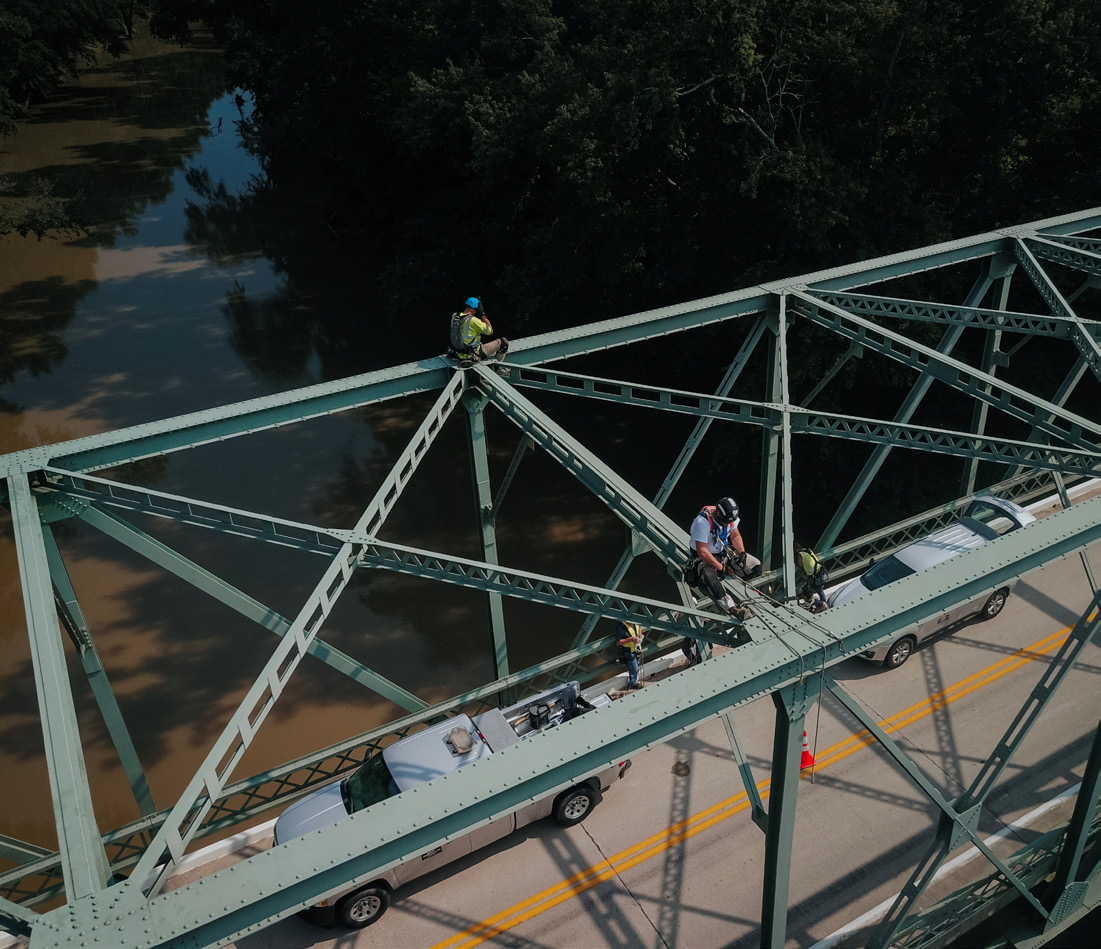
• Conduct structure inspections and give traffic engineers a real time, bird’s eye view of traffic flow.
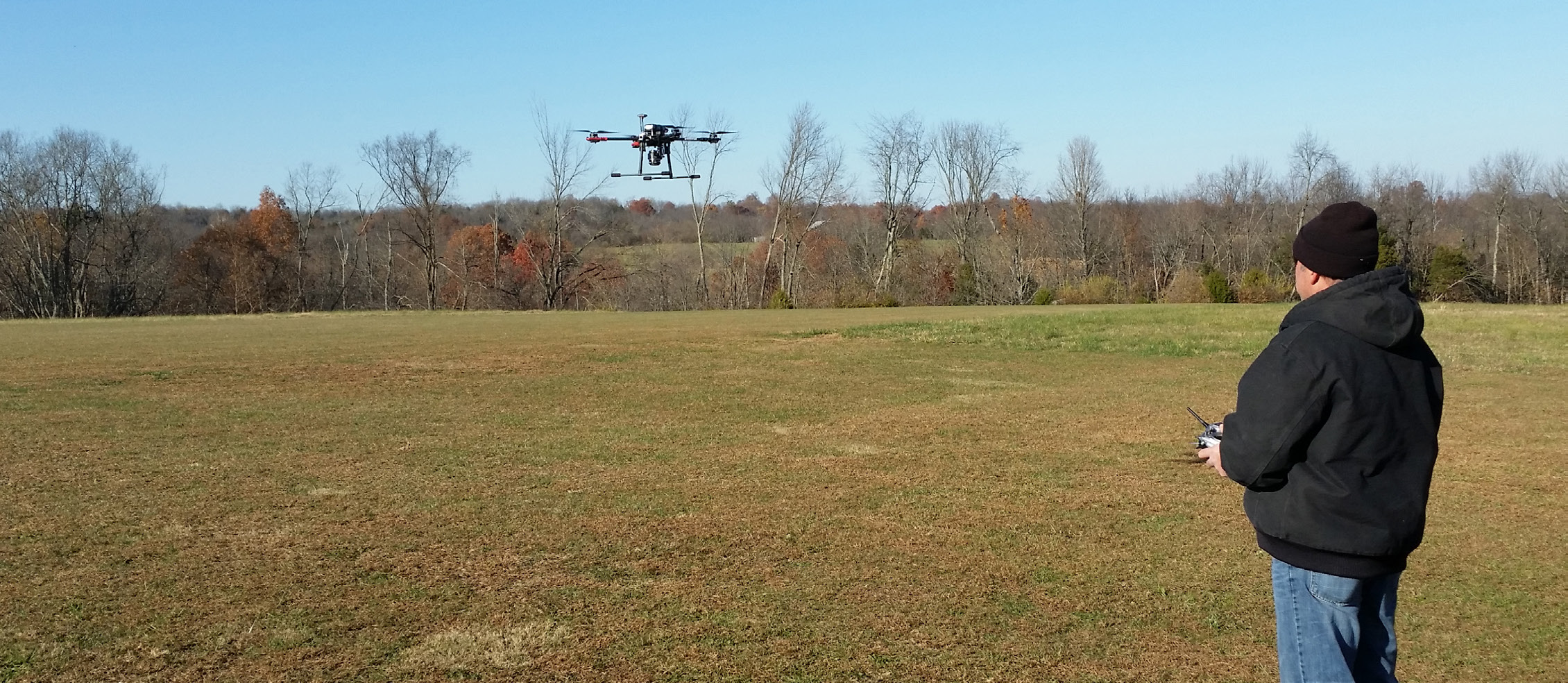
The Federal Aviation Administration (FAA) defines and regulates UAS as aircraft. This complicates efforts to deploy UAS for highway data collection. In 2016, new regulations (14 CFR Part 107) were released that permit the expanded use of small UAS. Both commercial (civil) and government (public) aircraft may operate under Part 107 rules. Public agencies may also elect to operate under a Certificate of Authorization (COA) or Waiver. Agencies operating under a COA must develop highly detailed policies, standards, procedures, operating areas, and training that achieves a level of safety equivalent to that specified in Part 107 Rules. Most agencies initially implement UAS pursuant to Part 107 and only develop a COA if necessary. COA operations are beyond the scope of this article. The vast majority of civil operations are conducted under Part 107 rules.
Part 107 rules are summarized below. These regulations continue to evolve; the latest information can be found at www.faa.gov/uas.
• Less than 55 lbs.
• Visual line-of-sight (VLOS) only
• No operations over unprotected non-participants or moving traffic
• Daylight or civil twilight with lighting visible for 3 miles
• Must yield the right of way to other aircraft
• First-person view (video from UAS) requires a visual observer with VLOS
• Maximum groundspeed of 100 mph
• Maximum altitude of 400 feet above ground level (AGL) or 400 feet above a structure
• Visibility of at least 3 miles
• Class G airspace only without air traffic control (ATC) permission
• One aircraft per pilot
• No operations from a moving aircraft
• No operations from a moving vehicle unless over a sparsely populated area
• No careless or reckless operations
• No carriage of hazardous materials
The FAA will consider waiving certain restrictions if a pilot can demonstrate that alternative methods provide an equivalent level of safety. The restriction on operating over moving traffic currently limits many highway applications; however, a new waiver proposal to allow flight over traffic is moving through the FAA rulemaking process.
Pilot Certificates and Registration
Pilots operating under Part 107 must hold a Remote Pilot Certificate, which is obtained by passing a written test at an FAA testing center. Unmanned aircraft must be registered with the FAA and display the registration number on their exterior.
Kentucky Revised Statutes 183.085, 500.130, and 511.100 contain UAS laws. Pilots should understand these Kentucky-specific laws.
The Kentucky Transportation Cabinet – Kentucky Department of Aviation (KYTC-KDA) provides assistance to state agencies operating UAS and functions as a single point of contact for statewide UAS operations. Questions concerning laws, regulations, pilot licensing, and drone registration should be forwarded to KYTC-KDA.
In addition to FAA regulations and Division-specific policy, KYTC Divisions and Districts must comply with the following guidance.
UAS Point of Contact (POC)
• Divisions and Districts shall designate a single POC for UAS. POCs should hold a Remote Pilot Certificate.
• UAS POCs shall participate in training, user group meetings, and other communications to develop and refine procedures, improve safety, and reduce duplication of efforts.
• UAS POCs shall maintain and provide a list of all UAS equipment, pilots, and their Remote Pilot Certificate numbers/expiration dates upon request.
• UAS POCs, in coordination with KYTC-KDA, shall develop procedures, checklists, and risk assessment tools specific to their operations, environment, and model(s) of UAS.
• UAS POCs shall coordinate flight operations in their area and provide first line training and support to pilots.
• UAS POCs shall investigate any UAS incidents, including unexpected UAS behavior that does not result in a crash. They shall communicate all incident information to the UAS user group to improve procedures, training, and maintenance to minimize future incidents. POCs shall ensure that pilots comply with FAA incident reporting procedures in their Division or District.
Pilot in Command (PIC) and Visual Observer (VO) Requirements
• PICs shall be able to manually fly the UAS and not overly rely on automated flight modes.
• PICs shall demonstrate to their UAS POC or designated flight instructor proficiency with each model/ system they are using and acquire at least 4 hours of flight time before the UAS is operated outside of a sterile environment. Flight time may be accrued at a suitable training site or at active project locations of sufficient size and remoteness to preclude injury to people or damage to private property.
• At least one VO shall be used whenever the UAS is flown at a non-sterile location. VOs shall be trained and competent in scanning for aircraft, interpreting UAS telemetry, controlling the flight area, and otherwise assisting the PIC.
• UAS flight crews shall wear appropriate attire during operations identifying them as state government employees.
Equipment
• UAS software and firmware shall be updated with the latest stable version. Test flights shall be performed at sterile worksites or training sites after major updates.
• State-owned UAS shall only be used for official state business. Personal UAS equipment shall not be flown for state production work.
• Divisions shall follow the Division of Equipment’s policies for inventory of UAS equipment.
• Equipment shall be registered and marked to meet FAA requirements.
• Equipment shall be appropriate for the application. Normally, the smallest and lightest available aircraft that meets the sensor requirements should be used.
Data
• Divisions and Districts shall follow KYTC UAS/GIS data storage and formats and standards.
• Divisions and Districts shall use Cabinet-developed standards, software, and forms for tracking flight operations, statistics, and equipment usage.
• Divisions shall develop policies and procedures specific to their operations to protect personally identifiable information (PII) captured with UAS. UAS shall not be operated in a manner that results in the intentional collection of PII, such as license plate numbers, addresses, and facial characteristics. Any such details shall be obscured or removed from photographs before they are copied to shared storage locations.
Each UAS type and configuration has advantages and disadvantages. To decide what UAS is best for a specific application, it is critical to understand the capabilities and limitations of each type. Primary aircraft types include:
• Fixed wing aircraft
• Rotary wing aircraft (helicopter)
• Multirotor aircraft
• Hybrid aircraft
Fixed Wing Aircraft
Fixed wing aircraft generate lift by moving forward through the air and only require forward thrust to overcome drag. Of those types listed above, fixed wing aircraft are the most efficient. They can generally fly longer and carry more payload than other types. The primary disadvantage of a fixed wing aircraft is they require a suitable takeoff and landing site. Most small fixed wing UAS are hand launched since smooth runway areas for rolling takeoffs are generally not available at project locations. Landing aircraft generally demands more space than takeoff because a clear upwind approach is needed. These aircraft seldom have landing gear, and most are skidded into the most suitable area. Small fixed wing drones are commonly constructed of expanded polypropylene or expanded polyolefin foam, which is commonly used in packing material; aircraft constructed with this type of foam can be very durable.
Rotary Wing Aircraft
Rotary wing aircraft (i.e., helicopter configurations) take off and land vertically and can hover in place. They are more efficient than multirotor aircraft due to their long and narrow rotor blades and are able to carry payloads too heavy for multirotor aircraft. Rotary wing aircraft are mechanically complex because the rotor blades constantly change pitch through each rotation. This cyclic pitch tilts the rotor disk in the desired direction. Collective pitch changes the pitch of all blades equally, varying the amount of lift provided by the blades. The combination of cyclic and collective pitch are adjusted through a set of linkages that connect to a swashplate (a rotating coupler). The swashplate tilts, providing cyclic pitch, while moving up and down the rotor shaft to provide collective pitch. Typical rotary wing aircraft have a tail rotor to counter the torque of the main rotor. A tail rotor requires a complex mechanism consisting of a drive shaft, gearbox, and variable pitch tail rotor blades. Although electronic stabilization systems have reduced the complexity of some of these mechanisms, rotary wing aircraft need more maintenance than other UAS types. One significant advantage of rotary wing aircraft is that they can be powered by a single motor, making them well-suited to internal combustion or turbine power. Fuel-powered aircraft can fly much longer than battery-powered aircraft due to the higher energy density of fuel.
Multirotor Aircraft
Multirotor aircraft generate lift through multiple pairs of counter-rotating propellers. Unlike fixed wing and rotary wing aircraft, multirotor aircraft cannot be flown without onboard sensors and microprocessors that continuously monitor altitude and constantly vary the speed of each motor to stabilize the aircraft. Multirotor aircraft usually have an even number of electric motors that turn fixed-pitch propellers. The torque generated by the propeller pairs turning one direction is countered by the opposing torque produced by propeller pairs turning the other direction. Pitch and roll movements are generated by varying the speed of the motors. A yaw motion is produced by varying the speed of propeller pairs to unbalance the torque in the desired direction. Multirotor aircraft are mechanically very simple, having as few as four moving parts. They are very reliable and easy to operate because mechanical complexity is replaced by electronics and software. Multirotor aircraft are generally battery powered and not as well suited to fuel power. For this reason typical flight durations are under 30 minutes.
Hybrid Aircraft
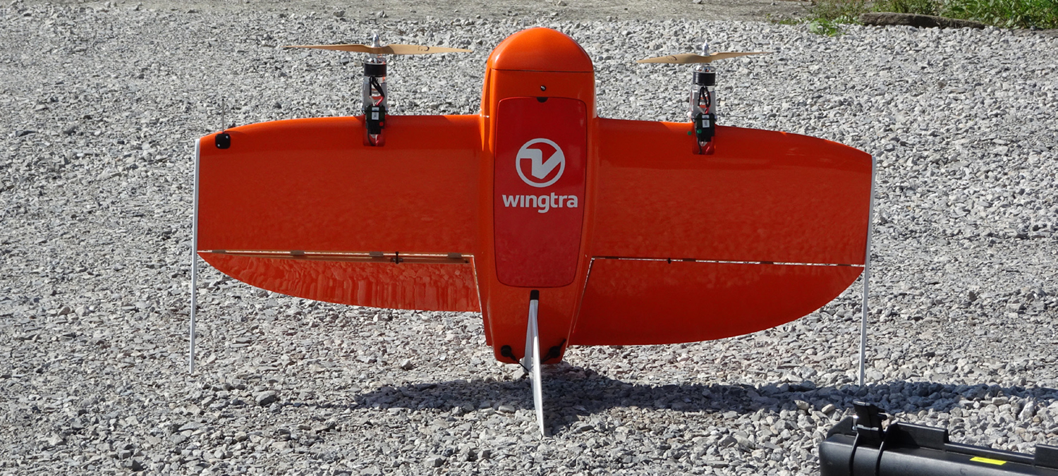
Hybrid aircraft combine a vertical takeoff and landing (VTOL) capability with the ability to transition to a more efficient fixed wing forward flight mode. Some hybrid aircraft use multirotors which are separate from the motor and propeller that provides forward thrust. These types of aircraft are called Separate Lift and Thrust (SLT). Lifting motors are turned off once the aircraft transitions to forward flight. Some hybrid aircraft rotate the lifting motors to a forward orientation when they shift into fixed-wing mode. Another configuration is the tailsitter, a fixed wing aircraft which receives sufficient thrust from multiple forward-facing motors to enable a vertical takeoff. Tailsitters are less mechanically complex because the motors do not articulate and yet provide VTOL and forward thrust. Automating the transition from hovering to forward flight and back again to hovering is challenging, and product performance hinges on a UAS having both proper aerodynamic and software design.
Table 1 summarizes the features of each type of UAS discussed above. However, the classifications may not be representative of every UAS make and model in each category as features vary by manufacturer. Before selecting a UAS, users should evaluate the performance, cost, and capabilities of products from several manufacturers.
| Table 1: Summary of UAS Features | ||||||
| Type | Payload Capacity | VTOL Capable | Complexity | |||
| Fixed Wing | High | No | Low | |||
| Multirotor | Moderate | Yes | Low | |||
| Rotary Wing | High | Yes | High | |||
| Hybrid | Low | Yes | Moderate | |||
The products most often acquired via UAS are aerial photos and video. Photos and video can aid in inspection, documentation, change detection, and many other purposes. Low-altitude photos and video yield valuable information about a site that is not apparent from ground observations. UAS typically fly at altitudes less than 400 feet above ground level (AGL). At this altitude, image resolution can be less than one inch — significantly better than what is obtainable via conventional aircraft photography. Wide angle lenses are most commonly used on UAS sensors and are less prone to vibration than longer lenses. The use of a gimbal to stabilize a wide angle lens yields very sharp images in a variety of lighting conditions. Sensors installed on a UAS benefit from having less atmosphere between the target object and sensor. This prevents interference from atmospheric haze that degrades the quality of aerial photographs captured at higher altitudes.
Structure from Motion (SfM) and Photogrammetry
Software that extracts three-dimensional (3D) information from two-dimensional (2D) images has transformed UAS into powerful mapping and surveying tools. SfM and photogrammetry are different techniques but provide similar products, such as georeferenced orthomosaics, point clouds, triangulated irregular network meshes, DEMs, digital terrain models (DTM), and contour maps. SfM uses images with a high level of overlap taken from various positions, to generate 3D models. Photogrammetry relies on calibrated cameras and known image positions to produce the products noted above.
A typical SfM workflow involves programming an aircraft to fly a series of parallel flight lines back and forth over the target object(s) to capture a series of images with at least 60 percent overlap front to back and side to side. This lawnmower-type pattern is adequate for producing representations of terrain with a high degree of accuracy. Objects with vertical facades not visible in straight down (nadir) images can be represented from photos taken at an angle that capture the facade. When mapping structures, a grid pattern consisting of two lawnmower passes at right angles to each other yields a model with greater detail. When attempting to capture a single structure, a series of circular orbits are made around the structure at two or more different altitudes and often combined with nadir images. Most drone flight planning software automatically calculates the flight lines, image intervals, and camera gimbal positions from a polygon or point of interest.
Because both techniques require matching features on the ground across multiple images, they are best suited for objects with adequate contrast and unmoving features. Water, vegetation swaying in the wind, and featureless surfaces (e.g., sand) cannot be modeled. Critically, SfM and photogrammetry techniques only measure what the camera sees. Point clouds obtained using these methods map the tops of trees and buildings. DEMs — bare earth models — cannot be obtained in areas with dense vegetation.
Aircraft movements can produce distortion with sensors and do not capture the entire image at the same moment in time. Most camera sensors read out an image one line at a time rather than all at once. Rolling shutter or electronic shutter sensors can introduce distortion because the camera-object relationship changes in the course of a single photo being taken. The use of fast mechanical shutters, gimbal motion compensation, and post-processing software that adjusts for rolling shutter distortion helps reduce errors in SfM and photogrammetry products.
Positional information is required to produce a scaled, geolocated 3D model. Products are georeferenced using one or more of the following methods:
• Navigational GPS
• Kinematic GPS
• Ground Control Points
Navigational GPS
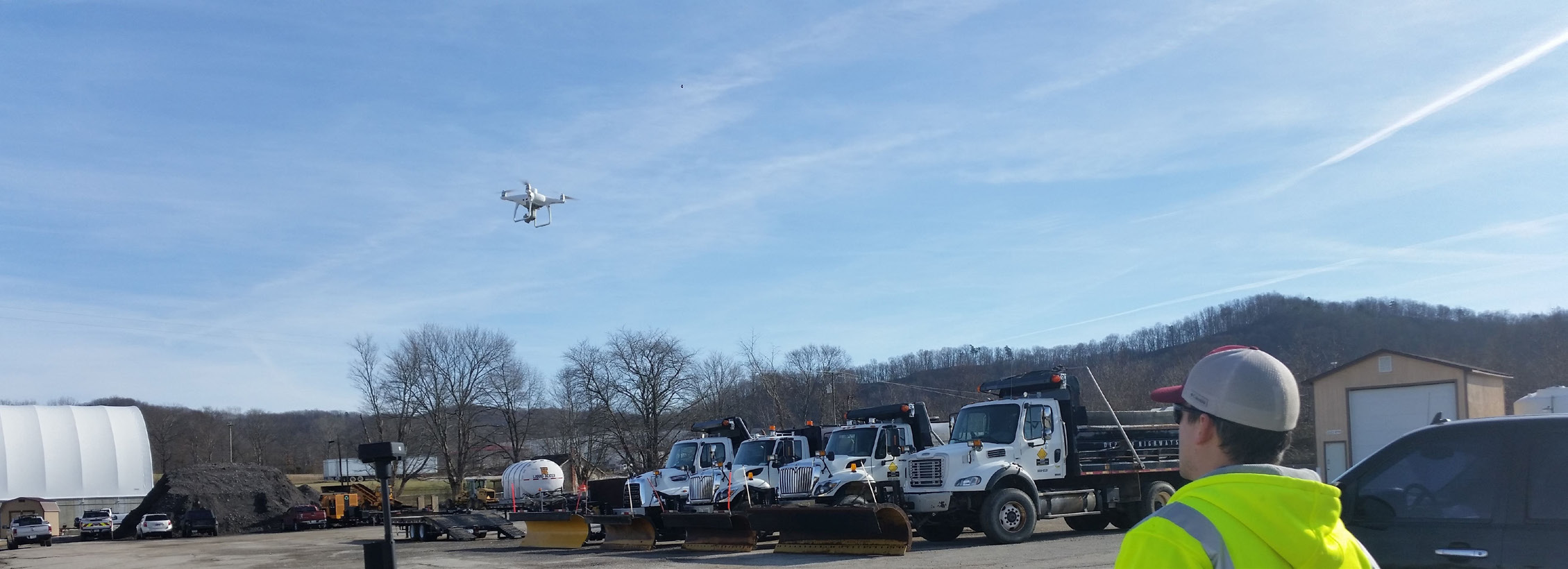
Most UAS have a navigational GPS that enables autonomous flight functions and allows them to hold their position. The most commonly used UAS insert GPS coordinates into the image Exif data. Despite navigational GPS potentially being accurate to only +/- 30 feet horizontally, SfM and photogrammetry software can produce scaled products suitable for some applications. The relative horizontal accuracy of a product processed with only navigational GPS can be fairly accurate.
Large vertical errors may result if ground control is not used. GPS units generally produce greater error in the vertical direction than in the horizontal direction. Most UAS obtain initial elevation data via GPS and use barometric altimeters during the flight. Significant vertical errors can result from errors in GPS elevation, changes in air pressure, and when equipment manufacturers use ambiguous vertical coordinate systems. With current technology at least one target is needed to correct the point cloud or DEM elevation.
Kinematic GPS
Real Time Kinematic (RTK) GPS units employ at least one additional GPS receiver at a known static position to continuously correct the airborne GPS position. They can generate horizontal data accurate to within a few tenths of an inch. Without ground control, UAS equipped with RTK can produce horizontal and vertical data accurate to +/- 0.5 foot. RTK also enables greater precision in aircraft movements and landings. One weakness of RTK GPS is that a brief loss of communications between the base station and aircraft can revert the airborne GPS to a less accurate floating mode, resulting in unusable image coordinates.
Post-Processed Kinematic (PPK) GPS does not require a continuous communication link between a base station and UAS, giving it an advantage over RTK. PPK uses raw logs from the onboard GPS, as well as logs from a local base station or network of Continuously Operating Reference System (CORS) receivers, to correct image coordinates after a flight. PPK methods can provide accuracies equivalent to RTK methods, however, they sometimes involve a more complex post-flight workflow.
Ground Control Points (GCPs)
Setting GCPs is an effective way to georeference UAS data. Surveyed ground targets are manually identified in the post-processing software. Temporary targets are often used, but features clearly visible in several photos can also be used as GCPs. Ground control is the gold standard because the 3D point cloud is corrected to surveyed points. Use of GCPs can produce vertical and horizontal accuracies of +/- 0.1 foot. Some software products give users the option to designate extra targets as check points. Check points are not used to georeference the point cloud, but they are used to measure error between calculated and surveyed coordinates.
Users must perform a quality check of all data generated from UAS. Licensed professional surveyors or other professionals with mapping experience can verify the accuracy of UAS data.
Multispectral Cameras
Multispectral cameras can sense near infrared (NIR) light above 1,000 nm. Multispectral cameras record separate images in multiple bands such as blue, green, red, and NIR. Some multispectral cameras use a separate lens, sensor, and filter for each band; others combine a single lens with a filter on the sensor. Multispectral cameras are commonly installed on UAS for the remote sensing of plant health. False color images that reveal plant health can be obtained by comparing the amount of light reflected in the NIR band to the visible red band. The ratio of NIR to visible light forms the basis of many vegetation indices, which disclose information about vegetation health not apparent from looking at normal photographs.
Infrared
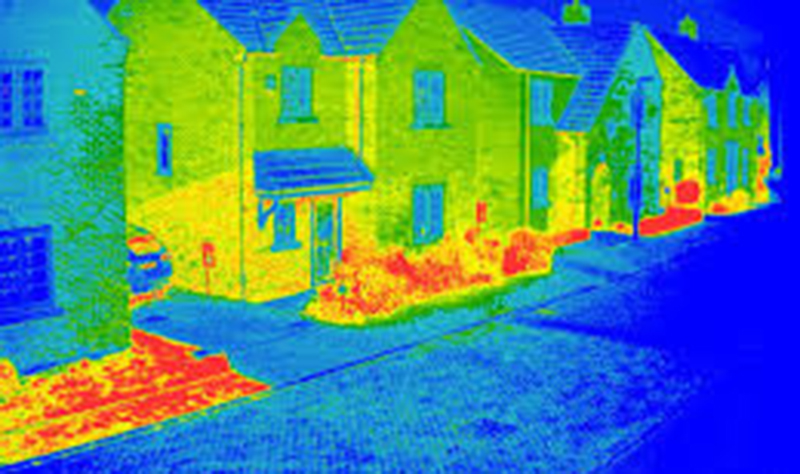
Infrared (IR) or thermographic cameras use a sensor that detects heat radiation in wavelengths as long as 14,000 nm. IR cameras positioned aboard UAS have multiple applications, including assessing heat loss from buildings, identifying underground archeological structures, evaluating seepage around dams, assessing pavement and bridge decks, and detecting people and animals. Using IR cameras carries some drawbacks. Compared to visible light cameras, they are more expensive and tend to have much lower resolution. IR cameras may also require active sensor cooling to reduce thermal noise. IR cameras can be paired with a visible light camera to enhance image details. Other IR cameras are available in radiometric versions which can output the temperature value of each pixel.
Light Detection and Ranging (LiDAR)
To measure distance, LiDAR sensors calculate the amount of time needed for a pulsed laser to reflect off a surface. Airborne scanning LiDAR systems make measurements millions of times per second. Scanning LiDAR systems with high point densities are often able to measure ground elevation through vegetation because a few light pulses reach the ground through gaps in the vegetation. LiDAR data are used to generate a point cloud with each point assigned a classification such as ground, water, vegetation, man-made object, or others. Classified point clouds are more easily manipulated because undesired features can be filtered out. Point clouds generated with LiDAR lack color information. But some manufacturers merge color image data from a camera to colorize the point cloud.
Western Transportation Knowledge Network for state surveys and domestics scans of UASs and UASs. https://transportation.libguides.com/uav/surveys
National Conference of State Legislatures for current unmanned aircraft state law landscape. https://www.ncsl.org/transportation/current-unmanned-aircraft-state-law-landscape
General overview of Unmanned Aircraft Systems
https://www.faa.gov/uas/
Summary of small unmanned aircraft rule (Part 107)
https://www.faa.gov/sites/faa.gov/files/2021-08/Part_107_Summary.pdf
FAA Drone Registration
https://faadronezone.faa.gov/#/
Know Before You Fly provides safety information and guidance to prospective UAS users
http://knowbeforeyoufly.org/
Remote Pilot – Small Unmanned Aircraft Systems Study Guide
https://www.faa.gov/sites/faa.gov/files/regulations_policies/handbooks_manuals/aviation/remote_pilot_study_guide.pdf
Advisory Circular for small Unmanned Aircraft Systems No: 107-2
https://www.faa.gov/documentLibrary/media/Advisory_Circular/AC_107-2.pdf


