
Search for articles or browse our knowledge portal by topic.
Bridge Railing and Guardrail Transition Sections
Contents
2. Introduction to Bridge Railing and Guardrail Transitions
3. Types of Bridge Railing in Kentucky
4. Types of Bridge End Transitions in Kentucky
5. Bridge Railing and Transitions in the Presence of Pedestrians and Bicyclists
6. Maintenance of Pre-MASH Bridge Railing and End Transitions
7. KYTC Reference Documentation
This article discusses bridge railings and transition sections, which are longitudinal barriers that connect railings to semi-rigid roadside barriers. It reviews the following:
- Bridge railings and transition sections often used for new construction in Kentucky
- Accommodations for pedestrians and bicyclists across bridges and culverts
- Past bridge railings and transition sections that may be encountered during maintenance activities
Full definitions of the following terms mentioned in this article can be found in the HKP Glossary:
Bridge Railing – A longitudinal barrier intended to prevent a vehicle from running off the edge of a bridge or culvert.
MASH – in HKP glossary.
National Highway System – in HKP glossary.
Transition Section – Provides a gradual stiffening of barrier from semi-rigid approach barrier to the rigid bridge railing.
Test Level (TL) – In HKP glossary.
Working Width – The distance between the traffic-facing side of a barrier before vehicle impact and the maximum lateral position of any major part of the barrier system or vehicle after the impact. Obstructions and fixed objects should be placed at or beyond the working width distance.
Bridge railings prevent vehicles from running off the edge of a bridge or culvert. They come in multiple shapes and sizes and are fabricated using a variety of materials, most often concrete or metal. Bridge railings differ from most other roadside barriers in that they are physically connected to a structure. Bridge railings can be designed to accommodate pedestrians and bicyclists.
Guardrail transition sections are longitudinal barriers used to join semi-rigid barrier (e.g., Midwest guardrail system) to rigid bridge railing. The transition section allows for the gradual stiffening between the rigid and semi-rigid systems. When a crash occurs between a rigid and semi-rigid barrier, this stiffening can reduce the potential for vehicle pocketing, snagging, or penetrating the system. Transition sections are not required when a rigid bridge railing connects directly to a rigid concrete barrier wall or when a semi-rigid bridge railing transitions to a guardrail. Both of these fabrication techniques are utilized in Kentucky.
Working in tandem, the bridge railing and transition section function as a barrier system (Figure 1), providing essential shielding at bridges while gradually increasing stiffness to ensure hardware is crashworthy.

Figure 1: Barrier Transition System
Bridge railings and guardrail transition sections are evaluated under AASHTO Manual for Assessing Safety Hardware (MASH) crash testing conditions. Railings and transition sections that pass testing are assigned a test level (TL) designation. Table 1 lists test conditions for each test level. KYTC Standard Drawings indicate bridge railing and transition section test levels using the abbreviation TL followed by a number: TL-2, TL-3, TL-4, and TL-5. Selection of an appropriate test level is needed to ensure a system will function properly under specified conditions.
For bridge railings, test level is selected based on two main factors: 1) whether the bridge is located on or off the National Highway System (NHS), and 2) anticipated roadway speeds. On the NHS, both new and modified bridge railings must be rated TL-3 or higher (FHWA, 1997). Off the NHS, TL-2 bridge railings can be used on low-speed roadways (≤ 45 mph). But for high-speed roadways (≥ 50 mph) off the NHS, TL-3 or greater bridge railings are needed.
For transition sections, test level is selected based on two main factors: 1) anticipated roadway speeds, and 2) location of the trailing transition section relative to the opposing traffic’s clear zone. On low-speed roadways (≤ 45 mph) TL-2 transition sections can be used. High-speed roadways (≥ 50 mph) require TL-3 transition sections.
On high-speed roadways, if a transition section is (a) used on the trailing end of a bridge (downstream to oncoming traffic) and (b) within the clear zone of opposing traffic, a TL-3 transition section must be used on the bridge’s trailing end.
| Table 1: MASH Test Matrix for Bridge Railings (RDG Table 7-1) | ||||||||
| Test Level (TL) | Test Vehicle Designation and Type | Test Conditions | ||||||
| Vehicle Weight kg (lbs) | Speed km/h (mph) | Angle Degrees | ||||||
| 1 |
|
|
|
|
||||
| 2 |
1,100C (Passenger Car)
|
|
|
|
||||
| 3 |
|
|
|
|
||||
| 4 |
|
|
|
|
||||
| 5 |
|
|
|
|
||||
| 6 |
|
|
|
|
||||
3. Types of Bridge Railing in Kentucky
The handrail subsection of the KYTC Standard Drawings — Bridges set provides details on bridge railings typically used in Kentucky (Table 2). The road designer, Division of Structural Design, and consultant (if applicable) must communicate and collaborate to ensure the bridge railing selected meets project-specific needs.
In addition to vehicle speeds and location (on or off the NHS), several factors influence the selection of bridge railings and transition sections. These include state standards, material availability, aesthetics, whether pedestrians and bicyclists are present, and the roadway’s functional and context classification. This section briefly reviews each bridge railing type and appropriate use cases.
| Table 2: List of MASH Bridge Railing Types in Kentucky | ||||||||||
| KY Bridge Railing Type | Test Level | Max. Speed (mph) | Use Conditions | Transition | Standard Drawing | |||||
| T631 Rail (6 ft, 3 in post spacing)* | TL-2 | 45 | On an 8 in or thicker deck with spread beams. Off of NHS. | Minimum 25 ft of guardrail at each approach end. | * | |||||
| T631 Rail (3ft, 1½ in post spacing) | TL-3 | Over 45 | On an 8 in or thicker deck with spread beams. | Minimum 25 ft of guardrail at each approach end. | BHS-012 | |||||
| Side Mounted MGS Railing | TL-3 | Over 45 | Use where side mounting is desirable. | Minimum 25 ft of guardrail at each approach end. | BHS-011 | |||||
| 40 in Single Slope Concrete Railing | TL-4 | Over 45 | Normal concrete barrier installation on all structures. | Requires Thrie-beam guardrail connector. | BHS-010 | |||||
| 36 in Single Slope Concrete Railing | TL-4 | Over 45 | Used where sight distance constraints require shorter rail. Used in combination with metal handrail installed on top. | Requires Thrie-beam guardrail connector. | BHS-009 | |||||
| Texas Type C411** | TL-2 | 45 | Used where historical railing is required. Off of NHS. | Requires Thrie-beam guardrail connector. | ** | |||||
| Texas Type C412** | TL-5 | Over 45 | Used where historical railing is required. | Requires Thrie-beam guardrail connector. | ** | |||||
|
||||||||||
3.1. T631 Railing
This railing mounts to the top of a bridge deck and is intended for use on decks with a thickness of at least 8 in. Standard Drawing BHS-012 depicts this railing with a post spacing of 3 ft 1½ in, which has a MASH TL-3 designation. It can be used on roadways with speeds > 45 mph and has a working width of approximately 58 in (TTI, 2014) as it contains and redirects an errant vehicle.
This railing cannot be installed on top of or behind curbs that project above finished grade, on bridges with expansion joints that provide more than 5 in of movement, on retaining walls, or on grade separations and interchanges.
No transition section is provided with this bridge railing, but at least 25 ft of guardrail extending past the bridge is needed at each corner to anchor the railing. More than 25 ft of guardrail may be needed for slope shielding depending on embankment height and length. The end of the guardrail is connected to an appropriate end terminal, which is chosen based on site-specific conditions.

Figure 2: T631 Bridge Railing (from BHS-012)
A TL-2 version of the T631 bridge railing is available for use on roadways off the NHS that have speeds ≤ 45mph. For this configuration, posts on the bridge are spaced 6 ft 3 in apart. If the T631 TL-2 version is used, the designer should contact the Division of Structural Design to facilitate plan development as no Standard Drawing exists.
3.2. Side Mounted Midwest Guardrail System (MGS) Railing
The Side Mounted MGS railing is used where side mounting of railing is desirable. Standard Drawing BHS-011 contains information on this railing. Posts on the bridge are spaced 3 ft 1½ in apart, which results in a TL-3 rating. This configuration has a working width of approximately 54 in (MwRSF, 2010) as it contains and redirects an errant vehicle. This rail cannot be installed on top of or behind curbs that project above finished grade, on bridges with expansion joints that provide more than 5 in of movement, on retaining walls, or on grade separations and interchanges. It can be used on roadways with speeds > 45 mph.
No transition section is provided for this bridge railing, but at least 25 ft of guardrail extending past the bridge is needed at each corner to anchor the railing. More than 25 ft of guardrail may be needed for slope shielding depending on embankment height and length. The end of the guardrail is connected to an appropriate end terminal, which is chosen based on site-specific conditions.

Figure 3: Side Mounted Midwest Guardrail System Bridge Railing (from BHS-011)
3.3. 40-Inch Single Slope Concrete Railing
With a height of 40 in (measured from the deck surface to the top of wall), this railing is integrated into the bridge deck and is used as the normal concrete barrier installation on all structures. Structural evaluations have shown the strength of this railing is equivalent to or greater than other single slope railings that have been crash tested to MASH TL-4 criteria.
When combined with a TL-2–rated approach guardrail transition section, it can only be used on roadways with speeds ≤ 45 mph. But when combined with a TL-3 guardrail transition section it can be used on higher-speed roadways. Standard Drawing BHS-010 provides information on this railing.

Figure 4: Typical 40-Inch Concrete Railing Section (From BHS-010)
3.4. 36-Inch Single Slope Concrete Railing
The 36 in (measured from the deck surface to the top of concrete wall) single slope concrete railing can be used if sight distance constraints require a shorter railing. In this situation either the steel (BHS-016) or aluminum (BHS-015) handrail is installed on top of the concrete railing. Like the 40 in single slope concrete railing, this railing is integrated into the bridge deck. Structural evaluations have shown the strength of this railing is equivalent to or greater than other single slope railings that have been crash tested to MASH TL-4 criteria. When combined with a TL-2–rated approach guardrail transition section, it can only be used on roadways with speeds ≤ 45 mph. If combined with a TL-3 guardrail transition section, it can be used on higher-speed roadways. Standard Drawing BHS-009 details this railing.

Figure 5: 36-Inch Concrete Bridge Railing with Metal Handrail (from Exhibit SD-9600 in Structural Design Guidance Manual)
3.5. Texas Type C411 and C412 Historic Railing
Two options are available if a bridge railing must simulate historic aesthetics to address environmental requirements (i.e., Section 106 of the National Historic Preservation Act of 1966; see Figure 6):
- If the bridge is off the NHS and speeds are ≤ 45mph, the Texas Type C411 railing can be used.
- If the bridge is on the NHS or speeds are > 45 mph, the Texas Type C412 railing can be used.
Each railing requires the use of an appropriate TL-rated transition system. Because these railings have unique openings, they need to be designed and detailed on a project-by-project basis. Contact the Division of Structural Design if historic railing is required on a project.

Figure 6: Historic Type Concrete Bridge Railing in Jefferson County
3.6. Other Railing Types
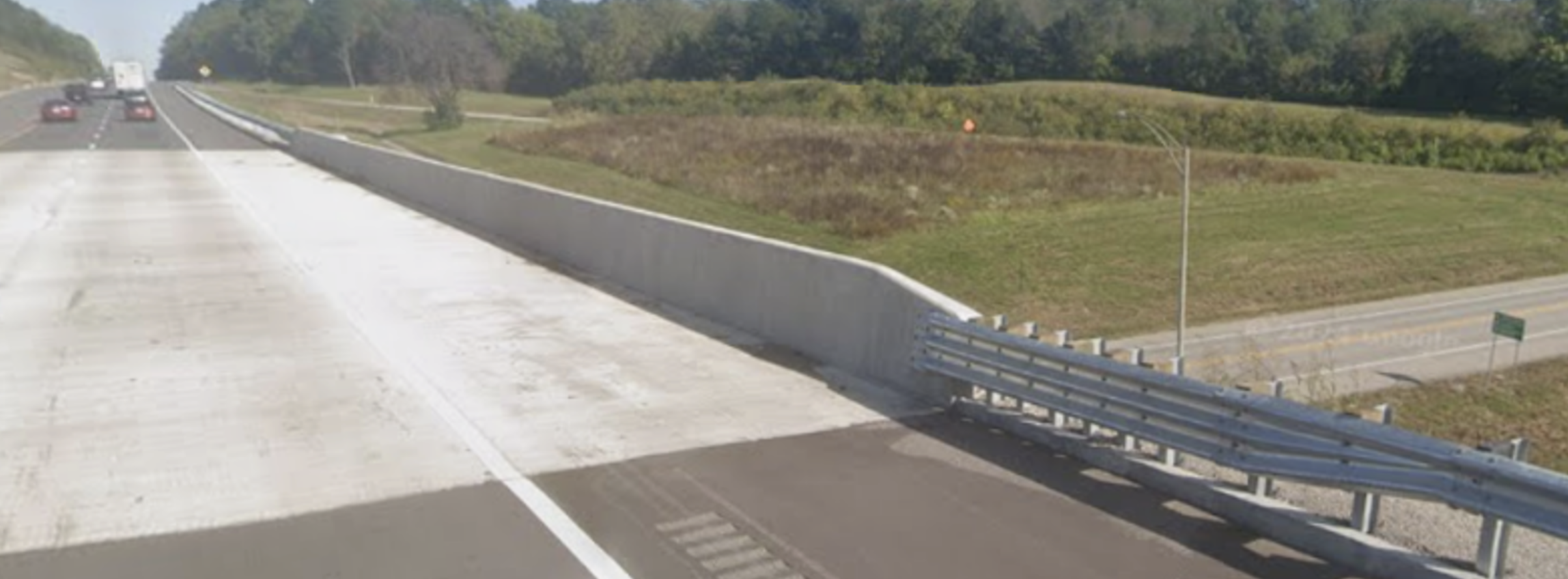
On high-speed roadways separated by a concrete median barrier, the height of bridge railing located in the median typically matches the height of the adjacent concrete median barrier. A transition section is not provided since a rigid median barrier wall connects to the rigid bridge railing (Figure 7).

Figure 7: Median Bridge Railing in Hardin County
Use of a bridge railing that differs from railings documented in Standard Drawings requires approvals from the Director of Division of Structural Design and the project team. Figure 8 provides an example of a railing not found in Standard Drawings — a decorative railing that is designed to blend in with a park landscape.

Figure 8: Decretive Bridge Railing on KY 715 in Red River Gorge
The handrail subsection of the KYTC Standard Drawings — Bridges set documents bridge end transitions commonly used in Kentucky (Table 3). Bridge end transitions can be placed on the upstream traffic approach to a bridge and on the downstream end exiting the bridge. As noted in Section 2, bridge end transitions are selected based on roadway speed and the location of the transition relative to the opposing traffic’s clear zone.
| Table 3: List of MASH Bridge End Transitions in Kentucky | ||||||
| Bridge End Transition Type | Test Level | Max. Speed (mph) | Standard Drawing | |||
| Thrie-Beam Guardrail Transition (TL-2) | TL-2 | 45 | BHS-013 | |||
| Thrie-Beam Guardrail Transition (TL-3) | TL-3 | Over 45 | BHS-014 | |||
4.1. Thrie-Beam Guardrail Transition (TL-2)
A MASH TL-2 Thrie-beam guardrail transition can be used to connect guardrail to bridge railing on roadways with speeds ≤ 45mph. On high-speed roadways, a TL-2 guardrail transition may be placed at the trailing end of a bridge railing if it is located outside the clear zone of opposing traffic. However, during future maintenance of traffic operations traffic patterns may shift, placing opposing vehicles within the TL-2 transition’s clear zone. Since TL-2 devices are designed for speeds up to 45 mph, if the temporary traffic control plan includes higher speeds, it is recommended to use a TL-3 transition at the downstream end of the bridge to accommodate this potential condition. Standard Drawing BHS-013 details the Thrie-beam guardrail transition. TL-2 and TL-3 versions of the Thrie-beam guardrail transitions differ primarily in terms of the length of Thrie-beam transitioning into the bridge railing. The TL-2 version has a shorter transition length (Figure 9). This guardrail transition can be used with or without curbing and a curb box inlet at the end of the bridge.
 (from BHS-013)")
Figure 9: Thrie-Beam Guardrail Transition (TL-2) (from BHS-013)
4.2. Thrie-Beam Guardrail Transition (TL-3)
The MASH TL-3 Thrie-beam guardrail transition can be used to connect guardrail to bridge railing on roadways when speeds are > 45 mph. Standard Drawing BHS-014 provides details on this guardrail transition (Figure 10). For the transition to function as intended, curbing is needed from the end of bridge railing to the seventh post. Curbing can be extended to a curb box inlet or flume at the end of the bridge if needed.
Figure 10: Thrie-Beam Guardrail Transition (TL-3) (from BHS-014)
If a roadway has pedestrian access routes, they should be accommodated across vehicular bridges. That is, if a sidewalk is located on the approaches to a bridge, a sidewalk should traverse the structure. Bridge railings to accommodate pedestrians must have a minimum height of 42 in. Where bridge railing includes openings (e.g., the use of metal handrailing atop a concrete railing), openings must be sized to prevent a 6-in diameter sphere from passing through them.
On low-speed roadways (≤ 45mph) a combination barrier in conjunction with a raised curb and sidewalk may be used. Curb height must not exceed 8 in. On high-speed roadways (≥ 50 mph), a MASH-tested railing should separate pedestrians from travel lanes.

Figure 11: Pedestrian Bridge Railing
Across a bridge, sidewalk width, where practical, should be equal to or wider than the clear width of the sidewalks that lead onto the bridge. The minimum clear width for sidewalk on a bridge is 5 ft, while minimum clear width for sidewalk immediately adjacent to the back of curb on a bridge is 6 ft.
If a ramp is needed to bring a sidewalk up to the grade of the bridge walkway, as per Americans With Disabilities Act (ADA) specifications found in the Public Right-of-Way Accessibility Guidelines (PROWAG), the maximum allowable ramp grade is 8.33 percent.

Figure 12: Pedestrian Bridge Railing (KY 3084 in Oldham County)
On bridges with bicycle facilities, the minimum height and minimum opening width for bridge railing are 42 in and 6 in, respectively. Typical bicycle facilities that cross bridges include bike lanes, separated bike lanes, paved shoulders, and shared use paths. Shy distances between the bicycle facility and continuous vertical elements (e.g., bridge railing and transition sections) along the edge of a bicyclist’s path should be at least 1 ft in width, with a width of 2 – 3 ft recommended.
If a bridge passes over another highway or a railway, a partial chain-link cage must be installed on top of the pedestrian-friendly bridge railing (Figure 13). Standard Drawing BGX-025 provides a similar detail.

Figure 13: Pedestrian Partial Cage over Railroad (KY 1848 in Shelby County)
6. Maintence of Pre-MASH Bridge Railings and End Transitions
Many bridge railing systems and transition sections were installed before MASH crash testing was implemented. These railings will remain in place for many years to come and will need to be repaired or replaced as they undergo structural deterioration or in response to damage caused by motor vehicle crashes. Contact the Bridge Maintenance/ Preservation Branch for guidance when a project has deteriorated or damaged bridge railing.
This section describes bridge railings and transition sections used on construction projects historically, but which have been replaced by newer types. Despite no longer being used on new construction, knowledge of these bridge railings and transition sections is needed to maintain existing systems. Section 7 links to Standard Drawings for these bridge railings and transition sections.
6.1. Railing System Type II
A side-mounted metal bridge railing that uses 25 ft of nested (two-ply) Guardrail-Steel W Beam (Single Face A) with closer post spacing as a transition section between the bridge railing and normal guardrail. This side-mounted railing is either mounted into a box beam or onto the slab.
6.2. Railing System Type III
A concrete safety shape (New Jersey) bridge railing integrated with the bridge deck. The top of the rail is 34 in above the driving surface. The end of the railing is designed to connect to a Guardrail Connector to Bridge End Type A or Type A-1.
6.3. Guardrail Connector to Bridge End Type D
A transition system used on bridges with concrete railing and a sidewalk. If needed, a concrete ramp can be provided to raise the sidewalk up to the bridge level. Closer post spacing and nested (two-ply) railing is used along the 25 ft leading into the bridge railing. This bridge end connector could also be used if a curb box inlet is present.
6.4. Guardrail Connector to Bridge End Type A
A transition system used on the upstream (facing oncoming traffic) side of bridges with concrete railings and on the downstream side of bridges where railing is located within the clear zone of opposing traffic. Closer post spacing, nested (two-ply) railing, and a rub rail is used on the 25 ft leading into the bridge railing. This bridge end connector could also be used if a curb box inlet is present.
6.5. Guardrail Connector to Bridge End Type A-1
A transition system on the downstream (traffic exiting) side of bridges with concrete railings located outside of the clear zone of opposing traffic (e.g., bridges on divided highways with a 40 ft depressed median). The 25 ft leading into the bridge uses nested (two-ply) railing but does not include a rub rail or reduced post spacing. This bridge end connector could also be used in the presence of a curb box inlet.
7. KYTC Reference Documentation
- Standard Drawings
- BGX-025 Chainlink Fence
- BHS-009 Railing System 36 Inch Single Slope
- BHS-010 Railing System 40 Inch Single Slope
- BHS-011 System Side Mounted MGS Details
- BHS-012 Railing System Type T631 Details
- BHS-013 Thrie-Beam Guardrail Transition (TL-2)
- BHS-014 Thrie-Beam Guardrail Transition (TL-3)
- BHS-015 Aluminum Handrail
- BHS-016 Steel Handrail
- BHS-007 Railing System Type II Guardrail System
- BHS-008 Rail System Type III
- RBC-004 Guardrail Connector to Bridge End Type D
- RBC-004N Guardrail Connector to Bridge End Type D Notes
- RBC-005 Guardrail Connector to Bridge End Type A
- RBC-005N Guardrail Connector to Bridge End Type A Notes
- RBC-006 Guardrail Connector to Bridge End Type A-1
- KYTC Structural Design Guidance Manual
- Chapter 302, Geometric Design Criteria
- Chapter 403, Section 2.3.2.2.2 Railings
- Exhibit SD-9600 Railing System 36-Inch Single Slope and Slab Details
8. References
Action: Crash Testing of Bridge Railings. (1997). Federal Highway Administration (FHWA). https://ftp.dot.state.tx.us/pub/txdot-info/brg/memos/fhwa/053097_crash_testing.pdf.
Bridge Standards. (2024). Texas Department of Transportation. https://www.dot.state.tx.us/insdtdot/orgchart/cmd/cserve/standard/bridge-e.htm
Development of a Low-Cost Energy-Absorbing Bridge Rail. (2010). Midwest Roadside Safety Facility (MwRSF). Report No. TRP-03-226-10.
Guide for the Development of Bicycle Facilities, Fifth Editon. (2024). American Association of State Highway and Transportation Officials. GBF-5. ISBN: 978-1-56051-820-4
Guide for the Planning, Design, and Operation of Pedestrian Facilities. (2021). American Association of State Highway and Transportation Officials. GPF-2. ISBN: 978-1-56051-608-8.
LRFD Bridge Design Specifications. (2024). American Association of State Highway and Transportation Officials. LRFDBDS-10. ISBN: 978-1-56051-828-0.
MASH TL-3 Crash Testing and Evaluation of the TxDOT T631 Bridge Rail. (2014). Texas A&M Transportation Institute (TTI). Test Report No. 9-1002-12-12.
Roadside Design Guide. (2019). American Association of State Highway and Transportation Officials. RSDG-4 2011. ISBN: 978-1-56051-509-8.
Safety Performance Evaluation of Weak-Post, W-beam Guardrail Attached to Culvert. (2014). Midwest Roadside Safety Facility (MwRSF). Report No. TRP-03-277-14.
Roadside Safety Knowledge Book:
Access the complete Knowledge Book here: Roadside Safety
Next Article:
Previous Article: