
Search for articles or browse our knowledge portal by topic.
Guardrail

A guardrail is a longitudinal, roadside barrier system that is installed to prevent errant vehicles from impacting roadside obstacles. By redirecting a vehicle departing the roadway, a guardrail keeps it away from more serious hazards, both constructed (e.g., sign structures, culvert inlets, utility poles) and natural (e.g., trees, rock outcrop). Guardrail prevents vehicles from descending a steep roadside embankment or veering into the roadway median and oncoming traffic. In some cases, guardrail is installed for reasons other than to safeguard motorists against obstacles (e.g., road closure barricades and barriers protecting pedestrians or sensitive areas).
When a vehicle impacts a guardrail, its driver and passengers encounter some risk. Guardrail does not eliminate the possibility of injuries or fatalities. A road engineer’s primary goal is to provide an adequate clear zone free of any obstacles and areas of concern. The only circumstance under which a guardrail should be installed is if it presents a lower risk to vehicles than unshielded roadside obstacles. Always consider alternatives to guardrail installation before deciding to install guardrail (e.g., removal or relocation of the obstacles). Where it is not practical to provide a full clear zone, the use of guardrail or another roadside barrier offers an attractive option as it significantly increases the safety of vehicles departing the roadway.
This article describes design, construction, and maintenance practices related to guardrail. In addition, it discusses selection procedures, maintenance of operational systems, and guidelines for upgrades.

Contents
5. Additional Guidance on Guardrail
6. Maintenance of Existing Guardrail Systems and End Treatments
7. Maintenance Activities in the Field Operations Guide
8. New Guardrail Installations
9. Contracts for Repair & Installation of Guardrail
10. Guardrail Recycling Program
1. Terms
The full definitions for terms included in this article (listed below) can be found in the HKP Glossary.
• Area of Concern
• Barrier
• Border Area
• Clear Zone
• Crash Tests
• Crashworthy
• End Treatment
• Guardrail
• Guardrail Post
• Length of Need (LON)
• Longitudinal Barrier
• MASH
• Midwest Guardrail System (MGS)
• NCHRP 350
• Nesting
• Reduced Post and Spacing
• Roadside
• Shielding
• Test Level (TL)
• Traveled Way
• W-Beam Steel Guardrail

2.1 Midwest Guardrail System
KYTC currently uses Midwest Guardrail System (MGS) for new installations of standard guardrail and corresponding end treatments. MGS is a non-proprietary steel or wood post W-beam guardrail system that meets MASH Test Level 3 criteria. The system adopts a typical W-beam guardrail with the following characteristics:
• 31-inch top of rail mounting height and tolerance of +/- 1 inch (see Section 3.5, Guardrail Height).
• Minimum 6-foot-long W6 x 9 steel posts or 6-inch x 8-inch wood posts
o Longer posts may be used (e.g., 7 feet or 9 feet) (see Section 5.1, Strengthening Guardrail).
• 6 inch x 8 inch routed or non-routed wood or composite plastic offset blocks
• Mid-span rail splices
o MGS relocates the splice (weakest link) away from the highest stress point at the post and blockout.
For MGS installations, contractors must use W-beam panels that are 12 feet 6 inches or 25 feet in length, but they may employ a 6-foot 3-inch panel at the end of the run.
2.2 Strong-post W-Beam Guardrail System
Prior to 2018 the standard guardrail in Kentucky was the strong-post W-beam. It consists of wood or steel posts that support a W-beam rail element blocked out from the posts. Blockouts are typically made of timber or composite plastic and are 6 or 8 inches deep and 6 inches wide. The strong-post W-beam meets NCHRP 350 Test Level 3 criteria and was mainly used before the adoption of MASH testing criteria. Strong-post W-beam guardrail systems have been installed at different heights, ranging between 27 to 29 inches.
Although the Cabinet has adopted MGS for all new installations, many miles of strong-post W-beam barrier have been installed based on previous NCHRP 350 guidance. Many of these systems have and should continue to have acceptable real-world performance. Raising all existing guardrail systems to meet current criteria is neither cost-effective nor practical. KYTC maintenance crews will continue to maintain strong-post W-beam guardrail systems until they reach the end of their service lives.
2.3 Alternative Guardrail Systems (Non-standard in Kentucky)
Other approved guardrail types may be used on Kentucky highways. Examples of alternative guardrail systems include the weak post W-beam, Weathering Steel Guardrail, and Steel Backed Timber Guardrail. If an alternative guardrail is utilized, it should be appropriate for the road context. Use of an alternative guardrail system requires written justification. The Division a project originates in — Division of Highway Design or Division of Maintenance — is responsible for reviewing and approving the use of alternative guardrail systems.
2.4 Temporary Guardrail Installations
Contractors that install a temporary guardrail during construction must comply with construction requirements for permanent guardrail.
Once the decision has been made to install roadside guardrail, details of the installation must be determined. Although the number of variables complicate placement of guardrail, there are some general guidelines that may be followed. The placement of guardrail pertains to the lateral and longitudinal position along the roadway.
3.1 Barrier Warrants
See the HKP article, Roadside Safety (coming soon), for a discussion of barrier warrants.
3.2 Length of Need (LON)
The LON is the length of barrier required to adequately shield the object or area of concern and prevent a vehicle from reaching the shielded feature. The length of guardrail must be sufficient to properly shield the object or area of concern, which is critical for roadside safety. See the HKP article, Roadside Safety (coming soon), for a discussion of LON.
During project design, the designer determines whether to install guardrail and calculates the LON. The LON is then used to lay out the guardrail system, and the designer notes on the plans where to install guardrail. If possible, designers should take steps such as flattening slopes with excess earthwork material (where field conditions allow) to reduce the need for guardrail. Refer to KYTC’s Standard Drawings and to AASHTO’s Roadside Design Guide guidance on lateral offsets, barrier deflection, terrain effects, flare rates, and LON.
KYTC measures guardrail quantity in linear feet. The distance is measured along the actual length of the rail between the limits of end treatments, terminal sections and bridge end connections, and crash cushions. Shop curved guardrail is measured in linear feet at 1.3 times the actual length.
Designers commonly design guardrail in to the nearest 12-foot-6-inch or 25-foot increment. A 6-foot-3-inch increment may be used if needed. Field conditions often differ from what plans depict, which can in turn affect the quantity of guardrail needed. Construction Engineers have the final responsibility for determining the placement and installed length of guardrail. A best practice for designers is to slightly overestimate guardrail length so that any construction field adjustments result in a negative-cost change order.
During construction, a guardrail is constructed to the alignment and at the locations shown in the Contract. Sometimes field conditions require that the amount and location of installed guardrail be adjusted. Before ordering guardrail materials, the Engineer and Contractor should meet on the job site to verify the LON and end treatment locations designated in the plans are appropriate for the field conditions. Adjustments should be made as needed. The LON, final location, and end treatment types are approved by the Construction Engineer.
Where possible, construction personnel should flatten earth-fill slopes using excess fill material to attain a clear zone and remove or minimize the need for guardrail. When laying out guardrail field installations, the Engineer should consult with the Roadway Designer when questions arise.
3.3 Minimum Guardrail Length
A guardrail installation should have a minimum length of 200 feet (including the end treatments) as this ensures adequate tensile strength for the system to perform well. In some cases, field conditions may warrant a shorter installation, which is acceptable. In these cases, consider strengthening the guardrail (see Section 5.1, Strengthening Guardrail). Similarly, if a guardrail will be installed prior to a fixed object, minimum guardrail length (including end treatments) should be 200 feet. Again, this length may be reduced if field conditions warrant.
3.4 Gaps in Guardrail Installations
Avoid short gaps between two guardrail installations. If connection gaps between barrier termini are less than 200 feet, the installations should be connected as a single run. Installing additional guardrail will be easier to maintain and less expensive than two end treatment installations. Exceptions may be necessary to provide access to locations behind the guardrail (for mowing and other maintenance tasks) or for other project considerations.
3.5 Height of Guardrail
Guardrail system performance is tied closely to the height of the W-beam rail element. Installation height is computed by taking a measurement at the center of the rail, at the bolt. Here, the height is measured from either the pavement surface, theoretical pavement, nominal terrain, or gutter pan to the top of the rail. A guardrail should be installed to the true gradient with no sags.
3.6 Where is the Height of the Guardrail Measured From?
The method used to measure guardrail height varies based on guardrail location. Five scenarios and their corresponding methods are described on the following page.

1) Guardrail installation is in the shoulder. The pavement surface (lane or shoulder) is flush with the guardrail’s face (i.e., its front).
• Measure from the pavement to the top of the W-beam rail.

2) Guardrail installation has 9-foot posts and 2:1 backslope at the posts.
• Use a string line or straightedge to extend the pavement lane/shoulder slope to the back of the rail; this is often called the theoretical pavement elevation. Measure from the theoretical pavement elevation to the top of the rail.

3) Guardrail installation is lateral to a recent pavement overlay.
• Follow guidance for Scenario #2. Resetting the guardrail may be necessary to achieve the proper height.

4) Guardrail installation is on a 10:1 or flatter slope of earthen terrain.
• Measure from the nominal terrain. Soils and fill-material used to create an embankment can be evenly graded, but the surface is rarely level and smooth enough for precise measurements normally used with paved surfaces to calculate guardrail height. Use a string line or straight edge to even out terrain variations.

5) Guardrail installation is slightly in front or aligned with the face of a curb.
• Measure from the gutter pan to the top of the W-beam rail.
3.7 Lateral Placement of Guardrail in the Shoulder
To give vehicles sufficient opportunity to recover without impacting an obstacle, place guardrail as far away from the traveled way as practical. Typically, guardrail is installed in the shoulder 2 feet from the slope break hinge point (see Section 3.10, Soil Backing). Narrow shoulders are often widened to facilitate guardrail placement.
The usable shoulder is the width available for vehicles to make an emergency stop or parking stop. The graded shoulder is distance from the edge of the travel lane to the normal slope break. Unless guardrail is present, typically the graded shoulder width is equal to the usable shoulder width. Once the usable shoulder width is established for a project and the decision has been made to install guardrail, the graded shoulder will need to be widened 3 feet 5 inches beyond the usable shoulder width to accommodate the guardrail installation. With the guardrail’s face located along the outside of the usable shoulder, the additional graded width provides 2 feet of soil backing behind the guardrail posts. If installing 2 feet of graded shoulder behind the posts is impractical, longer guardrail posts can be utilized.
For a discussion of shoulder width and slope, see the HKP article, Roadway Design Elements (coming soon).
Do not install guardrail posts in structural pavements that will restrict post movement during impact.
3.8 Lateral Placement of Guardrail Beyond the Shoulder
In some cases, guardrail may be installed closer to an obstacle rather than at the roadway shoulder edge. Installations of this type reduce the length of rail needed to shield the obstacle. Placing guardrail farther from the roadway lessens the probability of a vehicle impact. At the same time, when a vehicle strikes a guardrail it may have a higher encroachment angle. This is an undesirable condition.
Lateral placement of guardrail away from the shoulder edge is most applicable when small areas of concern are present (e.g., point-type obstacles such as overhead sign bridge supports and bridge piers).
Carefully select where to place guardrail installations on earthen terrain slopes. Judicious positioning will minimize the likelihood of an errant vehicle vaulting over a guardrail and improve the guardrail’s performance. MGS can be placed at any position on a slope (relative to the slope only) if the slope in front of the barrier is flat (i.e., 10:1 or flatter). This also applies to areas in front of the flared section of guardrail and the area approaching terminal ends.
Guardrail should not be placed on a steep slope. For slopes steeper than 10:1, see the HKP article, High-Tension Cable Barrier (coming soon).
3.9 Lateral Placement of Guardrail at Curb Face
While the use of curbs with guardrails is discouraged, curbs more than 6 inches in height should not be used with guardrail. By themselves, curbs typically cannot redirect vehicles, except for very low speed impacts. Placing a curb near guardrail can result in a vehicle vaulting over the barrier. The following guidance can assist in planning curb type and guardrail placement when the use of guardrail/curb combinations is unavoidable:
• For design or posted speeds of 45 mph and less:
o Construct the guardrail so its face is flush with the curb’s face. Avoid locating a curb in front of a guardrail. Consider reducing the curb height to 4 inches and stiffening the rail to reduce vaulting potential. (see Section 5.1, Strengthening Guardrail).
o If it is not practical to install the guardrail flush with the face of the curb, construct the guardrail with a minimum offset of 6 feet from the curb’s face to the guardrail’s face.
• For design or posted speeds greater than 45 mph:
o Facility designs should omit curbs. However, a mountable curb may be used at the edge of the shoulder if necessary. If guardrail is needed in this situation, construct it so the rail’s face is flush with the curb’s face.
3.10 Soil Backing
Considerable contribution to a guardrail system’s redirectional capability comes from the strength of its guardrail posts. As such, it is necessary to ensure a post has adequate geotechnical support to prevent it from pushing backward too easily. Kentucky’s standard guardrail installation requires the emplacement of at least 2 feet of fill at a maximum slope of 10:1 behind the rail. If placing 2 feet of fill material behind the barrier is not practical, longer post lengths (e.g., 7-foot) may be used (see Section 5.1, Strengthening Guardrail). For details, refer to the illustration at the right.

3.11 Working Width and Deflection Distance Behind Guardrail
A guardrail impacted by a vehicle laterally deflects in the direction of the crash force. How much it deflects depends on the stiffness of the guardrail system, vehicle speed, angle of impact, and vehicle weight. If a guardrail is to successfully redirect a vehicle, a clear area free of obstructions must be provided between the back of the rail system (e.g., back of posts) and the object or area being shielded. Design deflection distance is the minimum distance between the guardrail and shielded object that should remain clear. It is measured from the back of the guardrail system and is based on MASH crash test results of a pickup truck traveling 62 mph impacting a guardrail at a 25-degree angle. As deflections in the field can be much greater (or lower) depending on impact conditions, treat recommended design deflection distances as minimums. Where practical, provide greater distances between the back of the guardrail system (i.e., back of posts) and the shielded object or area. Carefully examine design deflection distance when deciding where to install guardrail. If a rigid object hazard is
present and the design deflection distance cannot be achieved, either strengthen the guardrail or use a rigid barrier system.


For strong post W-beam guardrail,
the recommended barrier placement
is a minimum of 4 feet from the front
face of the guardrail to the front of
the shielded object or area.
Deflection needs are addressed by
the working width. For MGS, working
width is the distance from the traffic
face of the W-beam before impact
and the maximum lateral position
of any major part of the guardrail or
vehicle during the impact to a rigid
object. The table below lists MGS
working width values for standard
installations and different post
spacings.
Unless otherwise noted in Table 1,
the MGS installation is standard
12-gauge W-beam rail, 31-inch from
top of rail, 6-foot-long W6 x 9 steel
posts, 8-inch offset blocks, mid-span
rail splices, and a minimum of 2 feet
of soil backing behind the guardrail
posts.
Table #1 MGS Working Width
| Application | Post Spacing | Working Width |
|---|---|---|
| Standard Post Spacing | 6' 3" | 5.0 feet (Front of guardrail to object) |
| One-Half Standard Post Spacing | 3' 1 1/2" | 4.5 feet (Front of guardrail to object) |
| One-Quarter Standard Post Spacing | 1' 6 3/4" | 3.0 feet (Front of guardrail to object) |
| 9' long posts, 2:1 back slope at post | 6' 3" | 5.5 feet (Front of guardrail to object) |
| Posts Placed at Hinge Point | 6' 3" | 6.5 feet (Front of guardrail to object) |
| Long Span Culvert Application | < or = 25' Opening 6' 3" for Other Posts | 8 feet (Front of guardrail to object) |
3.12 Rail Lapping
A guardrail is lapped in the direction of travel of the adjacent traffic. A vehicle snagging a reverse lapped guardrail during impact is unlikely, however, reverse lapping can hinder some maintenance activities (e.g., plowing snow). See Section 719.03.02 of the Standard Specifications for Road and Bridge Construction for more details.
3.13 Guardrail Sampling and Testing
Guardrail, guardrail end treatments, and all component materials can only be approved following (1) receipt of the manufacturer’s certification and field verifications, and (2) if required, destination sampling and laboratory testing. Laboratory testing must accord with procedures in the Materials Field Sampling and Testing Manual.
The project engineer is responsible for verifying that each shipment conforms to dimensional and zinc‐coating requirements. If field measurements indicate insufficient zinc coating, rail samples must be submitted for testing to the Materials Central Lab. Confirm that guardrail manufacturers are included on the List of Approved Materials.
If the end of barrier systems (e.g., guardrail) are located within the clear zone, they must be anchored and shielded with end treatments. Guardrail end treatments are frequently used to minimize the severity of impacts with fixed objects by gradually decelerating an impacting vehicle to a stop or redirecting it around the object of concern. Barrier end treatments should comply with MASH guidelines. AASHTO’s Roadside Design Guide provides specific information concerning barrier end treatments. KYTC’s Standard Drawings give specific details and applications of commonly used barrier end treatments.
4.1 Anchorage
Devices used to anchor a flexible or semi-rigid guardrail to the ground increase its tensile strength so that a vehicle is redirected during an impact. For guardrails to function properly, having sound anchorage at each end is critical.
A crashworthy end treatment is required when the end of a guardrail faces oncoming traffic and is in the clear zone. An anchor is installed as a part of the end treatment (see Section 4.2, Guardrail End Treatments). When the end of a guardrail is outside the clear zone for both directions of traffic, a crashworthy end treatment may be unnecessary. To anchor the guardrail in these cases, use a Guardrail End Treatment Type 2A Standard Drawing No. RBR-025 and the appropriate Guardrail Terminal Section RBR-010. Figure 1 depicts examples of Terminal Section No. 1.
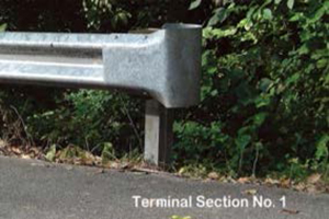
Figure 1a. Terminal Section No. 1
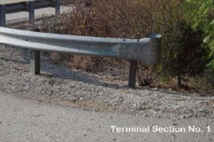
Figure 1b. Terminal Section No. 1
4.2 Types of End Treatments
KYTC uses the following guardrail end treatments:
4.2.1 Guardrail End Treatment Type 1
Standard Drawing No. RBR020 (Type in drawing # into table. Do not include any dashes or spaces.)
Energy Absorbing Straight-Line Terminal
Description and Considerations
• Type I End Treatments are energy-absorbing terminals used on single runs of MGS or strong-post W-beam. Energy absorbing terminals can stop vehicles quickly following a direct end-on impact (usually 50 feet or less; however, this varies based on terminal type, vehicle type, and vehicle speed).

End Treatment Type 1 MSKT TL3
• Redirection starts beyond the third post. If a vehicle impacts the guardrail in front of the third post it will pass through the structure.
• Adequate vehicle recovery area must be provided behind the treatment. Standard Drawing No. RBI004 (Type drawing # into table. Do not include dashes or spaces) contains grading details for the earth pad behind the End Treatment.
• Permissible alternatives for Guardrail End Treatment Type I include:
• Soft-Stop (Trinity Industries)
• MSKT (Road Systems Inc.)

End Treatment Type 1 Softstop TL3
4.2.2 Guardrail End Treatment Type 3
Standard Drawing No. RBR030 (Type drawing # into table. Do not include dashes or spaces)
Barrier Anchored in Backslope Terminal
Description and Considerations
• Type 3 End Treatments are a non-proprietary guardrail end terminal.
• Type 3 End Treatments terminate a W-beam guardrail installation by burying the end in the backslope. They are bolted and anchored to a concrete block or guardrail anchor post, all of which are buried.
• Type 3 End Treatments are non-gating, and the entire system is designed to redirect a vehicle.
• Earthwork grading is critical for a buried-in-backslope terminal because the terrain leading up to guardrail must be traversable and contain no fixed-object hazards.

End Treatment Type 3
4.2.3 Guardrail End Treatment Type 4a
Standard Drawing No. RBR035 (Type drawing # into table. Do not include dashes or spaces)
Energy Absorbing Flared Terminal
Description and Considerations
• Energy-absorbing terminals used on single runs of MGS or strong-post W-beam. They have up to 4-foot offset at the approach end and require a larger platform for installation.
• Energy-absorbing terminals can quickly stop vehicles following direct end-on impacts, (usually 50 feet or less; however stopping distance varies based on terminal type, vehicle type, and vehicle speed).
• Redirection begins beyond the third post. If a vehicle impacts the guardrail in front of the third post it will pass through the structure.
• Adequate vehicle recovery area must be provided behind the treatment. Standard Drawing No. RBR-035 contains grading details for the earth pad behind the end treatment.
• Permissible alternatives for Guardrail End Treatment Type 4a include:
o MFLEAT (Road Systems Inc.)

End Treatment Type 4A MFLEAT TL3
4.2.4 Guardrail End Treatment Type 7
Standard Drawing No. RBR050 and RBR051 Turned-Down End Terminal (Type in drawing # into table. Do not include dashes or spaces)
Description and Considerations
• Type 7 End Treatments are a non-proprietary guardrail end terminal.
• This end treatment is not crashworthy. It is used as a last resort on low-speed/low-volume roads when other crashworthy end treatments will not function properly.
• The W-beam guardrail is twisted from the first post to a terminal section bolted to a concrete anchor block or a steel anchor plate and post. The contractor may choose which type of end anchor to install.
• Retain appropriate justification in the project file when this treatment is used.
• Never use Guardrail End Treatment Type 7 on high-speed National Highway System (NHS) routes. It may be an option on low-speed/low-volume facilities when an adequate recovery zone is unavailable or where conditions preclude other end treatment types from attaining their desired performance.

End Treatment Type 7
4.3 Choosing an End Treatment
Designers should consider the following hierarchy of guidelines when selecting a leading-end barrier end treatment:
• Barrier anchored in backslope (Guardrail End Treatment Type 3)
o When properly designed and located, this type of anchor fully shields the hazard, eliminates the possibility of an end-on impact with the guardrail terminal, and minimizes the likelihood of the vehicle passing behind the rail.
• Flared terminals (i.e., Guardrail End Treatment Type 4a)
o Use of a flared breakaway guardrail end treatment with adequate clear zone behind the gating device provides room for recovery.
• Straight-line terminals (i.e., Guardrail End Treatment Type 1)
o Use of a straight-line delineated breakaway end treatment with adequate clear zone behind the gating device provides room for recovery.
When selecting an end treatment for the guardrail’s trailing end, make sure the decision factors in the clear zone are needed for vehicles traveling in the opposite direction.
4.4 Earthwork Grading for Guardrail End Treatments
Proper earthwork grading around guardrail end treatments supports their proper function. Grading between the traveled way, the terminal, and the approach in front of the terminal should produce a surface that is as flat as possible (typically this is the shoulder slope extended). Grading behind a gating end treatment should be properly addressed to allow errant vehicle recovery. Consult Standard Drawings Nos. RBI-002, RBI-003, RBI-004, RBR-030, and RBR-035 for more information. Areas approaching and immediately adjacent to guardrail end treatments should be no steeper than 10H:1V. Steeper adjoining slopes should be gently transitioned to a flatter slope to minimize rollover potential.
4.5 Crash Cushions
Crash cushions are sometimes used to shield the end of a guardrail run, particularly double face guardrail installations. They shield the end of a barrier or fixed object by gradually decelerating a vehicle to a safe stop or redirecting it away from the object.
Crash Cushion Type VI or Type VII is preferred for installations on paved surfaces. Placement of this device requires use of a concrete pad and a bolt-down system (see Standard Drawings Nos. RBC110, RBE060 and RBE100). (Type drawing # into table. Do not include dashes or spaces)
• Crash Cushion Type IX or IXA is preferred for installation on earth surfaces. This device requires posts and soil tubes (see Standard Drawings Nos. RBB002, RBE200 and RBE205).
Refer to the HKP article, Crash Cushions (coming soon), for more details.
5.1 Strengthening Guardrail
Occasionally a guardrail system must be strengthened to reduce the design deflection distance. For example, a transition section is needed where a guardrail attaches to the approach end of a rigid concrete bridge rail (See the HKP article, Barrier Classifications (coming soon)). A guardrail must be stiffened if a rigid object obstacle is present within the design deflection distance. Standard installations can be modified using the following techniques to strengthen the guardrail:
• Add a rubrail
• Install additional posts (reducing the post spacing) (See MGS Working Width Table in Section 3.11.)
• Use extra length posts (e.g., 7-foot or 9-foot posts, not the standard post length of 6 feet)
• Use thicker gauge posts (e.g., 10-gauge posts instead of 12-gauge posts)
• Double nest the rail
• Bolt a W-beam to back of the posts
For extra length posts and nested guardrail, quantities should be measured and bid items provided. Consult Section 719 of the Standard Specifications for Road and Bridge Construction for additional information. Where extra strength is needed different methods may be combined (e.g., when the area of concern is near the back of rail).
5.2 Transitions and Connectors
A guardrail is classified as a semi-rigid barrier due to its deflection distance upon crash impact (see the HKP article, Roadside Safety (coming soon), for a discussion on barrier categories). A transition section is needed when a guardrail connects to a rigid barrier (e.g., bridge railing or concrete barrier) or rigid object (e.g., bridge pier or sign structure). The transition should provide a gradual, continuous stiffening of the guardrail system from a less rigid to more rigid system. This reduces or prevents a vehicle from snagging or punching through the barrier. Use of a cast-in-place anchor or through-bolt connection is recommended to ensure the connections are as strong as the barrier itself.
Use TL-2 or TL-3 Thrie-Beam Guardrail Transitions to connect W-beam guardrail to concrete bridge rails, rigid barriers, or rigid objects. The TL-2 railing transition should be used when speeds are 45 mph or less. The TL-3 railing transition must be used when speeds are over 45 mph. For more details, see Standard Drawings Nos. BHS013 and BHS014 (Type in drawing # in the table. Do not include any dashes or spaces.).
Historically, the Guardrail Connector to Bridge End Type A was used on both bridge ends on undivided highways and on the approach bridge ends of divided highways. A Guardrail Connector to Bridge End Type A1 was used on the exit bridge ends of divided highways. A Guardrail Connector to Bridge End Type D was applied on each end of a bridge on which a sidewalk was present or its installation was proposed on the structure (and not on the roadway). This only applied to rural structures having two-direction traffic with a sidewalk.
Type A, A1, and D connectors are no longer installed on new highway construction. When repairing or restoring existing concrete barrier wall and these guardrail connectors, see Standard Drawings RBC004, RBC005, RBC05N, and RBC006. Refer to the RBB and RBC series of Standard Drawings in the HKP article, Bridge Railings and Transitions (coming soon), for more details.
On some retrofit projects use of standard guardrail connectors may not be appropriate. Contact Central Office Division of Maintenance for guidance.
5.3 Delineation of Guardrail
Delineators must be installed on new guardrail. Standard Drawing No. RBR055 (Delineators for Guardrail) illustrates delineator elements, placement, and spacing. Section 830 of the Standard Specifications addresses retroreflective requirements for guardrail delineators.
The District is responsible for deciding (1) whether to install new delineators on existing guardrail systems which lack delineation or (2) whether it is necessary to replace existing guardrail delineation due to non-reflective and/or missing delineators. High-priority locations for guardrail delineation include curves and ramps on freeways and expressways, as well as guardrail sections located in the median. The District may elect to place delineation to indicate openings at entrances on highways.
Where a guardrail end treatment adjacent to the roadway is marked, a Type 3 object marker is typically used. Alternating stripes of Type 3 object markers should slope downward, toward the side on which traffic is to pass. Generally, the end treatment manufacturer supplies Type 3 object markers. Use retroreflective sheeting that conforms to the size of the approach end.
5.4 Double Faced Guardrail Installation
Double-faced guardrail has two W-beam rails configured as a single beam on each side of post. It is typically used in the median in place of concrete barriers, particularly when the required shielding length is relatively short. Double-faced guardrail is also used when a guardrail may be exposed to impacts from either side. When installed near the pavement edge, it is critical for the area between the posts to be free of asphalt.
5.5 Extra Blockouts
On longitudinal guardrail installations, double blockouts (up to 16 inches deep) may be used to increase the post offset to avoid obstacles such as curbs. There is no limit on the number of posts that can have double blockouts installed.
Do not employ double blockouts for transitions and terminals, unless approved by the manufacturer. Under special circumstances (e.g., avoiding buried obstacles that are not relocated), additional blockouts may be installed to obtain up to 24 inches of clearance (three 8-inch blockouts or two 12-inch blockouts) for one or two posts in a section of guardrail. Standard Drawing RBR-031 (Guardrail End Treatment Type 3 Pipe Drainage Detail) offers an example of using extra blockouts.
5.6 Omitted Post
Omit a post only under special circumstances and only on a standard run of guardrail. Omitting a post requires the construction engineer’s approval.
Single posts may be omitted along runs of MGS W-beam guardrail without the system needing modification (i.e., no weakened posts, no nested rail elements, no special posts). Always consider the following issues before taking this step:
1. At least 50 feet is required between omitted posts, a terminal, or other special design.
2. Omitted posts cannot be used within transitions, terminals, or special designs.
3. No curbs are present where guardrails are installed.
4. Additional deflection resulting from the omitted post.
5.7 Short Radius Curved Guardrail at Intersections and Driveways
Occasionally, an intersecting side road or driveway is located so close to a side obstacle that installing a minimum length MASH TL-3 guardrail is infeasible. This most occurs often at bridge ends. A short radius curved guardrail installation may accommodate this situation. See Standard Drawing RBI001 for more details.
Keep the following in mind when designing a short-radius curved guardrail:
• Installations at intersections and driveways can create nuisance hit problems for turning traffic (e.g., tractor trailers turning off of or onto side roads, farm implements turning into and out of field entrances). Check turning patterns to ensure a guardrail installation will not significantly affect turning movements.
• Installations at intersections and driveways can obstruct motorist sight, especially if the side road or entrance is at or near the crest of a vertical curve. Perform sight distance analysis for both plan and profile views to determine what effects guardrail installation may have on motorist line-of-sight.
5.8 Guardrail in Border Area Behind Curb
On roadways where the design speed is between 30 and 45 mph and there is a curb adjacent to the traveled way (e.g., urban and suburban roadways), keep the border area free of obstacles. Any decision to use a guardrail within the border area should be informed by careful evaluation. A guardrail used in the border area should present less of a hazard than the obstacle it shields. See Chapter 10 of AASHTO’s Roadside Design Guide for further guidance on clear zones in urban areas.
5.9 Guardrail Posts in Rock
Use the appropriate omitted-post design (as discussed above) if rock is present where a single guardrail post is to be installed. If rock is present at several points where posts will be installed, place the posts in cored holes (see Section 719.03.01 of the Standard Specifications for Road and Bridge Construction).
5.10 Acidic Fill Material
When shales are used in embankment fill sections, acidic shale is generally encased inside the embankment. At least 4 feet of nondurable shale or clay soil should be placed atop the embankment to control the corrosion of guardrail posts. It may be appropriate to install corrosion-resistant guardrail posts. See Special Note 8N Corrosion Resistant Guardrail and the Geotechnical Guidance Manual GT-609-5 on Acid-Producing Shales.
5.11 Retention of Soil Backfill
Horizontal lagging walls are often used for temporary or permanent retention of soil material and other backfill. Lagging may consist of wood, guardrail, or geogrid. When backfill is placed or compacted behind the guardrail wall, it is imperative that rails not to be damaged.
Lagging has traditionally been designed based on experience or empirical methods. (e.g., the Federal Highway Administration uses the Goldberg Zoino chart). Contact the Geotechnical Branch for more information.
Guardrail systems must be kept in good working condition if they are to function correctly when impacted by a vehicle. Crash damage and environmental degradation can result in some deterioration of guardrail. Superficial damage will not measurably affect barrier performance. Other forms of damage may seriously degrade performance (see Longitudinal Barrier Damage and Terminal Damage sections). Prioritize repair efforts on damage which impacts guardrail performance.
6.1 Program Overview
The Division of Maintenance prepares and administers an annual Guardrail Improvement Program. Funding is allocated to locations on the State Primary, State Secondary and State Supplemental Highway Systems where guardrail installations (1) garner the highest cost-effectiveness rankings and (2) can be built without major roadway reconstruction. Always consider the use of guardrail alternatives (e.g., hazard removal or relocation, flattening slopes, pipe extensions); these may be included and funded by the program.
The Maintenance Rating Program (MRP) uses roadway condition surveys to systematically identify maintenance needs. As part of the MRP, guardrail systems are evaluated to determine if guardrail section height does not meet specifications, whether outdated end treatments are present, and identify any damage to the guardrail system.
Guardrail maintenance is funded through the annual maintenance budget, with anticipated work included in the maintenance work program. This funding cannot be used to upgrade substandard or obsolete guardrail or new guardrail installations.
6.2 Routine Maintenance of Guardrail
The items listed below qualify as routine maintenance of existing guardrail systems and end treatments. County crews, District special crews, or price contract vendors perform this maintenance.
• Minor straightening
• Bolt tightening
• Damage repairs
• For replacement of individual guardrail elements when galvanizing or paint is severely deteriorated, use the following
guidelines:
o New or re-galvanized rail may be installed on existing postso Painted rail must not be used
o Rail must be of equivalent section and equal or greater gauge as that replaced
• Replacing guardrail sections
o Note: This item may be considered a maintenance expenditure when the rail is significantly low (i.e., less than 27 inches) or where the posts or rail have deteriorated to the extent that the system would not contain an errant vehicle. In these cases, normal repair consists of removal, adding some or all new posts, and replacing the system. The cost would approach that of full replacement. If replacement is cost-effective and funds are available, it is the preferable option. This type of work is usually a bid contract.
• Removing guardrail at locations where it is not warranted by current standards
o Concurrence by both the Chief District Engineer (CDE) and the Director of the Division of Maintenance is advisable if rail will be removed but not replaced.
6.3 Repairs to Existing Strong-post W-Beam Guardrail
Repairs to damaged strong-post W-beam guardrail are made in accordance with Standard Drawings RBI-001 and RBR-001. Manufacturer specifications should be followed when repairing damaged guardrail end treatments. If full replacement of a guardrail end treatment is necessary, install a MASH-compliant guardrail end treatment pursuant to the current Standard Drawings RBR-Series. If a guardrail system merits full replacement, it must be replaced using MGS in accordance with the current Standard Drawing RBR-001. The Standard Drawing titled Guardrail System Transition illustrates how to transition existing strong-post W-beam guardrail to MGS. Transition length varies based on existing guardrail height:
• If the height of the existing guardrail is 29 inches, a 12-foot-6-inch transition is used to achieve a 31-inch rail height.
• If the height of the existing guardrail is 27 inches, a 25-foot transition is used to achieve a 31-inch rail height.
If the damaged portion of guardrail is minimal or the length of damaged guardrail is less than the required transition length needed, replace the damaged guardrail with in-kind strong-post W-beam.
6.4 Reimbursement for Repairs Due to Vehicular Crashes
When guardrail is replaced after it has been damaged in a vehicle crash, the District Office and Office of Legal Services can work jointly to recover reimbursement costs. Funds recovered are returned to the Road Fund.
FOG (Field Operations Guidance) Activity Codes for guardrail repair are C300, C330, C390 and C400. These codes address the performance of guardrail repair by state forces or contractor crews. Additional information can be found here in the Field Operations Guide.
Kentucky Transportation Center (KTC) researchers published Warrants and Guidelines for Installation of Guardrail based on materials from the AASHTO Roadside Design Guide. The Cabinet subsequently developed and implemented a standardized program based on this information. KYTC has used these standardized guidelines to support a more uniform review and prioritization process for locations that warrant guardrail. During the standardized review, each location that meets warrants are assigned hazard index points. Guardrail installations at locations of need are prioritized based on the number of hazard index points they receive. KYTC can thus spend limited resources available under this program at the most hazardous locations. Locations on the Rural Secondary System are sorted and identified by county designation; locations on the State Primary, Secondary; and Supplemental Systems are identified by District designation.
Deviations from approved design plans, current Standard Drawings, or the KYTC Active Sepia List must be reviewed and approved by the CDE and the Director of the Division of Maintenance.
• Decisions to install guardrail at a new location on the Rural Secondary System are based on the amount of available funds, cost-effectiveness, and hazard index points for all Rural Secondary locations in a specific county.
• Decisions to install guardrail at a new location on the State Primary, Secondary, or Supplemental Systems are based on the amount of available funds, cost-effectiveness, and hazard index points for all State Primary, Secondary, and Supplemental locations in a specific District.
Once funding is available for guardrail projects at new locations, the Executive Director of the Office of Rural and Secondary Roads approves recommended projects for the Rural Secondary System. The State Highway Engineer approves recommended projects for the State Primary, Secondary, and Supplemental Systems.
Generally, projects should not require utility relocation. If utility impacts are possible, reconsider the project design or scope to avoid utility impacts. It may be necessary to locate utility facilities in the field during development so they can be avoided.
When adequate equipment and personnel are not available to repair guardrail, Districts have the option of using master agreement contracts to perform the repairs. The Division of Maintenance works with the District and Division of Purchases to establish master agreements for guardrail repairs. If repairs are performed by contract on Federal-aid projects, all federal requirements (e.g., Davis-Bacon Act, Buy America) must be met. (Follow this link for more information on prevailing wage rates, coming soon.)
Except for emergency repairs, master agreements should not be used to install large quantities of new guardrail at a single location, or on a single project that could be let as a construction project, unless the master agreement bid prices are less than the construction contract unit bid price.
The Division of Maintenance administers a continuous recycling program that salvages materials when guardrail is removed during construction or reconstruction projects, repairs, or other activities. Districts maintain stockpiles of used guardrail components. Section Engineers complete Form TC 63-72 (Guardrail Delivery Verification Sheet) for guardrail which leaves a project. Standard Specifications 719 and 814 address guardrail in construction contracts, including removal and salvaged material. The Bailey Bridge Yard Representative receives the shipment, counts all material, and documents the quantity received.
The Division of Maintenance arranges for salvageable posts and rails to be re-galvanized. Before requisitioning new materials, Districts notify the Division of Maintenance that additional guardrail components are required and determine if recycled materials are available.
KYTC does not install guardrail for the sole purpose of protecting adjacent private property. Doing so creates an unnecessary roadside hazard. If property owners install guardrail on their property, KYTC is not responsible for its maintenance, repair, or replacement.
The Permits Manual describes requirements for encroachment permit applications that will impact existing guardrail systems.
• AASHTO’s Roadside Design Guide
• “Guardrail 101” (PDF). U.S. Department of Transportation. Federal Highway Administration. Archived from the original (PDF) on 2015-01-05. Retrieved 2017-11-14.
•https://safety.fhwa.dot.gov/roadway_dept/countermeasures/faqs/qa_bttabr.cfm#brrs11
• Kentucky Standard Specification for Road and Bridge Construction
o Section 719 Roadside Construction – Guardrail
o Section 814 Materials Details – Guardrail Systems
• KM64-116, Standard Operating Procedure for Acceptance of Guardrail Systems
• KYTC Field Operations Guide
o Activity C300, C330, C390 and C400
• KYTC List of Approved Materials
• KYTC Standard Drawings
o RBI001 through RBI009, RBR001 through RBR010, and RBR025 through RBR050
o KYTC Active Sepia List
• Per Highway Design Web Page
• 2009 MUTCD with Revisions 1 and 2, dated May 2012, published by FHWA at: https://mutcd.fhwa.dot.gov/kno_2009r1r2.htm
