Search for articles or browse our knowledge portal by topic.
KYTC’s 2+1 Roadway Design Guidance
A 2+1 road is a three-lane highway that has two travel lanes in one direction – one of which is used for passing maneuvers – and one lane in the opposite direction. The passing lane alternates every few miles. On some highways, traffic volumes are insufficient to justify a four-lane highway but are too great to be served by a two-lane configuration with permitted passing (when a vehicle can safely pass another) or a two-lane configuration which has occasional added-on passing lanes. In these conditions, a continuous passing lane whose directionality alternates is less stressful for drivers than finding a passing gap in oncoming traffic and minimizes the likelihood of head-on collisions with opposing vehicles. 2+1 roadways can be a good option in these situations.
2+1 configurations have several objectives:
- Provide systematic passing opportunities along a highway corridor. Improve traffic operations on two-lane highways by breaking up traffic platoons.
- Increase average travel speed along a corridor. Average travel speed in the passing lane is increased, and the speed benefits of passing lanes continue downstream of the lane.
- Reduce delays resulting from the inability to pass, either due to passing restrictions or limited gaps in the opposing traffic stream. Passing lanes typically reduce the percent time-spentfollowing (PTSF). PTSF is the average percentage of total travel time vehicles travel in platoons behind slower vehicles because they cannot execute passing maneuvers on a two-lane highway. This benefit can persist for some distance downstream of the passing lane and improve level of service.
- Improve safety by providing passing opportunities that do not require a passing driver to use the opposing traffic lane. This reduces the risk of head-on collisions and improves road safety relative to two-lane highways.
- Reduce costs and environmental impacts compared to adopting a four-lane configuration.
Disadvantages of 2+1 configurations include:
- Increased potential of high-speed differential conflicts with vehicles leaving or entering the roadway at intersections and access points.
- Compared to two-lane highways, greater risk of sideswipe crashes where vehicles merge at transitions from two-lanes to one.
- Possible safety concerns at traffic volumes close to capacity. Higher flow rates reduce the average gap between vehicles, which forces drivers to merge into smaller gaps.
- When transitioning from two lanes to one lane with high traffic volumes, merging is difficult and capacity goes down.
- Opportunities to pass slow vehicles are prohibited in single-lane sections.
Symmetrical 2+1 roadways maintain a continuous three-lane cross section. The road’s center lane uses pavement markings to establish a passing lane which changes directionality throughout the corridor. Asymmetrical 2+1 roadways add a third lane for passing on the outside of a two-lane roadway. Either configuration can be used to improve traffic flow. Compared to a two-lane highway with the same traffic volume, 2+1 roads generally operate at least two levels of service higher and have lower crash rates. They are a cost-effective option for reconstructing two-lane highways with high traffic volumes but which are not sufficient to warrant a full four-lane facility. Figure 1 shows conceptual drawings of symmetrical and asymmetrical 2+1 configurations.

Figure 1: Asymmetrical and Symmetrical 2+1 Configurations
When a passing lane is added to a two-lane, two-way rural highway, its operational effectiveness depends on the length of the passing section and spacing between passing sections. It is desirable to have a passing lane section that can convert platoon flow at its upstream end to free-flowing single vehicles at its downstream end.
For any passing lane application, a minimum passing lane length of 0.5 miles is recommended — a shorter lane is not effective at reducing vehicle platooning. The maximum recommended passing lane length is 2 miles — a longer lane is less effective and has a lower benefit/cost ratio. Table 1 lists the optimal passing lane lengths based on one-way flow rates. These lane lengths do not include passing lane tapers at the beginning or end of passing lanes. Designers may need to vary lengths to account for site-specific factors (e.g., addressing safety-related issues).
Table 1 Optimal Passing Lane Lengths for Traffic Operational Efficiency
| One-Way Flow Rate (veh/h) | Recommended Passing Lane Length (mi) |
|---|---|
| 100-200 | 0.5 |
| 201-400 | 0.5-0.75 |
| 401-701 | 0.75-1.00 |
| 701-1,200 | 1.00-2.00 |
Source: AASHTO Green Book
2+1 configurations provide a viable design alternative for high-speed rural highways that have moderate traffic volumes. They can be used on a new alignment or retrofitted on an existing alignment. A 2+1 configuration should be considered the ultimate design for roads with a design year volume of 15,000 ADT (Average Daily Traffic) or less. If the design year volume is 15,000 – 20,000 ADT, a 2+1 configuration may be used as the initial design, but right of way should be purchased to accommodate expansion to a four-lane facility. If the large increase in the forecasted traffic volume never materializes, a four-lane section need not be built. Typically, roads with a design year volume less than 5,000 ADT will not benefit from a 2+1 configuration.
A 2+1 configuration is generally not recommended if flow rates exceed 1,200 veh/h in one direction of travel — effective merging operation is maintained at lane drops when flow rates are equal to or less than 1,200 veh/h. A four-lane roadway is generally more efficient at high traffic flow rates. To decide whether an existing two-lane highway should be converted to a 2+1 configuration or a four-lane facility, a traffic engineering analysis should be performed. This analysis should determine the number of lanes required to achieve a targeted volume-to-capacity ratio. The Highway Capacity Manual outlines procedures for performing operational analysis and assessing roadway capacity.
Even though a 2+1 road is expected to be a consistent three-lane facility, it may be narrowed along the corridor based on project needs and constraints. For example, the three-lane section may be reduced to two-lanes along a short distance when passing over bridges or through deep cuts where a three-lane fullwidth cross section would significantly increase project costs. A two-lane configuration may also be used on a section to avoid environmental impacts.
Key design considerations for 2+1 roads include passing lane length, operational direction, and the location of transitions. It is unlikely passing lanes will simply alternate directions every other mile. Instead, the design team must carefully examine geometric, operational, and site-specific factors when developing a 2+1 concept throughout the roadway corridor. Designers should be flexible when choosing passing lane locations. Ideally, their placement should maximize operational effectiveness and minimize construction costs. Factors to consider when designing a 2+1 road are listed below.
- A 2+1 configuration should only be used in level or rolling terrain. In mountainous terrain and on isolated steep grades, the most appropriate placement is climbing lanes on uphill grades.
- When choosing the passing lane’s operational direction, pay close attention to grades. Uphill grades are preferred but not required. As the highway grade lengthens and steepens, traffic operation benefits from having the two-lane operation on the uphill grade. Evaluate traffic operations including truck volumes if consideration is given to terminating passing lanes on uphill grades.
- Safe and effective passing lane operations require adequate sight distance on the approach to lane additions and lane drop tapers.
- Provide stopping sight distance continuously along a 2+1 roadway.
- Consider decision sight distance at intersections and lane drops.
- Avoid closing a passing lane over a hill or around a horizontal curve where the pavement surface at the end of the taper is not visible from the beginning of the taper.
- Preference for passing is normally given to traffic departing an incorporated area. Providing access in this manner accords passing opportunities as vehicles leave congested areas and can serve as a traffic calming measure as vehicles enter the town through the one-lane section.
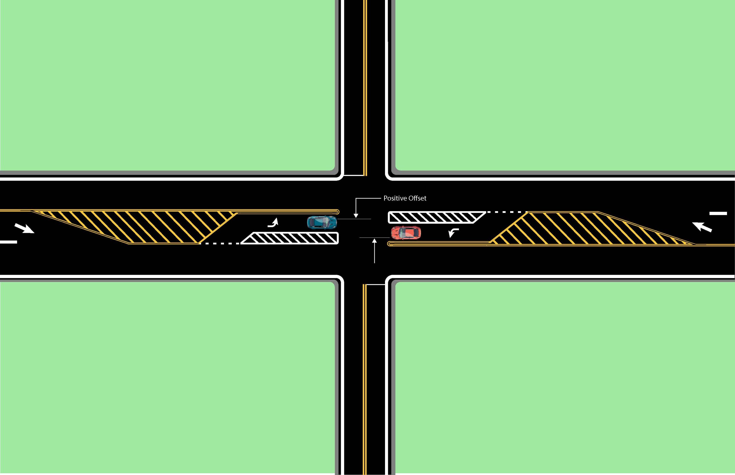
- Passing lanes should be located away from major intersections and high-volume driveways to decrease the probability of speed differentials between turning and passing traffic. Major intersections should be located in the transition area between opposing passing lanes, and conventional left-turn lanes should be provided at the intersection. Low-volume intersections and driveways may be accommodated within passing lanes sections but not within taper transition areas. See 2+1 Roadway Access Management for more information.
- Exercise caution when applying the 2+1 concept to an existing roadway with low-speed curves. Because the 2+1 configuration increases travel speeds and encourages passing, review geometric factors (e.g., horizontal curve radius, superelevation) to determine whether they are adequate for the anticipated operation, or if improvements are needed to match the facility’s design speed.
- Passing lanes are most effective when drivers enter the right lane at the lane transition and only use the left lane when passing a slower vehicle. Therefore, geometric design and pavement markings along the transition should encourage drivers to enter the right lane.
- When ending a 2+1 section and transitioning from three lanes to two lanes, allow adequate distance (recommend stopping sight distance) between the end of a lane closure taper and obstacles such as guardrail or guardrail end treatments, narrow bridges, or high-traffic intersections.
Transitions between passing lanes in opposing directions require careful design. Intersections, bridges, auxiliary turn lanes, and appropriate pavement markings in medians can be used to establish a buffer between opposing passing lanes.
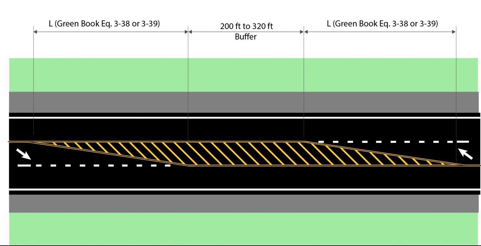
Transitions which begin or end the passing lane should be located where drivers have full view of the change. A head-to-head transition is located immediately downstream of a lane drop. It is called headto- head because vehicles in the middle lane head toward each other before merging into the right lane. Therefore, a buffer between vehicles traveling in opposite directions is needed. A minimum buffer of 200 feet should provide adequate warning and stopping distance to accommodate opposing vehicles that cross their lane reduction taper and enter the transition area. For example, where the pavement markings establish a lane drop, a 12-foot lane and 55 mph speed limit would require a taper distance of 660 feet. Adding one-half the buffer zone length (100 feet) means the distance from the start of the passing lane transition to the middle of the head-to-head transition should be 760 feet. In this scenario, a vehicle traveling 55 mph would need more than nine seconds to proceed from the beginning of the lane reduction taper to the middle of the buffer zone. Taper distance, pavement markings, and centerline rumble strips should be adequate to alert errant drivers and give them enough time to take corrective action. The Green Book recommends a 320-foot buffer between the end of each lane drop, which may be more appropriate for higher ADT routes or those with higher percentages of truck traffic.
A tail-to-tail transition is located immediately upstream of a lane addition. With tail-to-tail transitions, vehicles in the middle lane head away from each rather than toward each other.
Lane drops (Figure 2) and additions (Figure 3) are illustrated below.

Figure 2: Schematic for Head-to-Head Transitions on a 2+1 Roadway

Figure 3: Schematic for Tail-to-Tail Transitions on a 2+1 Roadway
The Green Book provides equations to compute lane-drop taper length. Equation 3-38 from the Green Book is applied where the posted or statutory speed limit is greater than or equal to 45 mph, while Equation 3-39 is used if the posted or statutory speed limit is less than 45 mph.
(3-38) L = WS for S ≥ 45 mph
(3-39) L = (WS2) / 60 for S < 45 mph
where: L = Length of lane-drop taper (ft) W = Width (ft) S = Speed (mph)
The recommended length for the lane addition taper is one-half of the lane-drop length.
Intersection placement should (1) minimize turning movements within passing lanes or (2) provide dedicated right- or left-turn lanes (see the Highway Design Manual HD-902). Access management considerations for 2+1 configurations are listed below.
- Provide right- and left-turn lanes in passing lane sections in the same locations they would be provided on a conventional two-lane highway.
- Low-volume intersections and driveways may be accommodated within passing lane sections.
- Reduced turning-lane warrants should be considered when the road context calls for extra safety measures (e.g., adequate sight distance is not available at an intersection, several entrances are close together, or there is a high posted speed (≥45 mph) and high flow rate).
For example, when these situations exist, the project team might decide to add left-turn lanes for any access with a projected peak hour left-ingress turning volume greater than 10 vehicles per hour (veh/h). Right turn lanes could be added for any access with a projected peak hour right-ingress turning volume greater than 25 veh/h.
- One strategy for the provision of turn lanes is using one lane in the three-lane section (i.e., transition to single-lane operations each direction and use the third lane as the auxiliary lane). Another strategy is to widen the road (i.e., build four lanes to create the extra pavement width needed for an auxiliary lane).
- Along a three-lane section, intersections with conventional left-turn lanes should be located in the transition areas between opposing passing lanes. This minimizes turning traffic volume in passing lanes (Figure 4) and allows the passing lane to switch direction. (See the Traffic Operations Guidance Manual for details on pavement markings.)
Figure 4: Schematic for Four-Leg Intersections on a 2+1 Roadway (updated 4/2/25)
- In some circumstances, designers can select a two-way left-turn lane (TWLTL) to address left turns from the mainline. For example, in short sections where a 2+1 configuration passes through a rural town or area with multiple driveways on both sides of the road, a TWLTL could be provided in the middle lane.

Figure 5: Schematic for Two-Way Left-Turn Lane on a 2+1 Roadway
- Placing entrances that require left-turns within the first 1,000 feet of a passing lane is sub-optimal because higher speeds and overtaking maneuvers are most common in this area.
- Do not locate entrances in areas with lane drops, tapers, or transitions.
- An alternative strategy for turning movements is permitting only right-in/right-out access. Section 9.9 (Indirect Left Turns and U-turns) of the Green Book reviews alternatives to left-turn lanes.
- Where growth and development are expected, 2+1 road designs should include an area concept plan for future land development. Prospective frontage roads and their intersections with a 2+1 road can be planned and indicated on highway plans as future construction. In this case, purchasing access rights from adjacent properties should be considered. This approach can be used to create full access control between major intersections, improving the corridor’s long-term safety. If access rights are purchased, alternative access points to the public street system should be provided to affected properties.
Appropriate lane and shoulder widths are determined in the same manner as for conventional two-lane highways — through a consideration of functional class, volumes, and speeds. For more information, see the Highway Design Manual (HD-702.10).
- In general, a 2+1 road’s lane width should match the lane width on adjacent sections of a two-lane highway.
- When site or budget constraints dictate a narrower cross section, the project team should determine where to reduce cross section elements based on traffic volumes, roadside conditions, geometric alignments, and crash data.
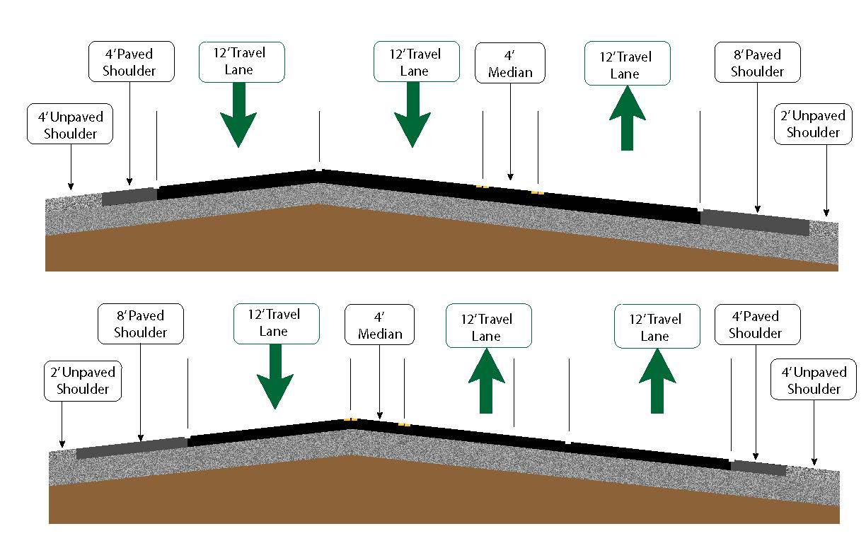
- Use typical shoulder widths throughout the length of the passing lane unless a reduced shoulder width would substantially reduce costs or avoid significant impacts. Shoulder widths may differ between the passing lane and the single lane side. For example, the paved shoulder width could be 8 feet on the single lane side and 4 feet on the passing lane. If the typical section has to be narrowed, the single lane side should have the wider shoulder.
- Whenever practical, the shoulder width in a passing lane section should not be narrower than the shoulder width on adjacent two-lane sections.
- Consider providing full shoulders (8 feet – 10 feet) in areas with high driveway density.
Passing lanes can operate effectively with no separation between opposing lanes of travel. However, some separation is preferable. A flush median separation of 4 feet between the opposing directions of travel is preferred (where feasible). Center line rumble strips and pavement markers are recommended on all 2+1 roadways.
Locating the pavement’s crown is one of the more complicated design issues on 2+1 roadways. Where an existing two-lane highway is restriped or widened to a 2+1 configuration, the crown may be placed within the traveled way. An existing highway may also be widened on one side only, resulting in the crown being located at a lane line. For new construction, the crown should be placed at a lane boundary. If it is necessary to transition the crown point along the roadway, it should be done along the lane drop or lane addition tapers. Figure 5 illustrates recommended crown locations.
Issues related to superelevation should be handled the same on a 2+1 road as on a comparable two- or four-lane undivided road.

Figure 6: Example 2+1 Road Typical Sections
Clear signage and pavement markings are essential to the operation of 2+1 passing lanes. Signing and marking plans should be developed for 2+1 facilities. The plans should be coordinated with the Division of Traffic Operations and be developed in compliance with the Traffic Operations Guidance Manual and the latest edition of the Manual on Uniform Traffic Control Devices.
Due to the unique design features of a 2+1 facility, additional public involvement activities are encouraged to inform residents and businesses of the proposed design’s benefits and intended use. For more information and ideas on public involvement, see the Highway Design Manual (HD-601) and KYTC’s Public Involvement Toolbox: (https://transportation.ky.gov/PublicInvolvementToolbox/Pages/default.aspx).


