Search for articles or browse our knowledge portal by topic.
Pipe Installation
Culverts and storm sewers are the two types of water conveyance systems most frequently used on roadway projects. Culverts are placed under roadways to convey water flowing in a ditch or natural stream from one side of the road to the other. A storm sewer is a system of two or more inlet structures connected by a pipe that collects runoff from the pavement. Kentucky uses several types of material for culverts and storm sewers.
Culvert and storm sewer pipes are categorized as rigid or flexible. A rigid pipe provides most of the strength to carry the earth and live loads, while a flexible pipe relies on the soil envelope around the pipe to adequately support loads. Existing soil conditions can affect the performance of both types, so it is critical that the pipe bed is properly prepared. While flexible and rigid pipes need to be monitored to ensure they perform as intended, flexible pipe installation should be closely monitored, as backfill provides a large portion of the structural integrity.
- Reinforced concrete pipe (RCP) is the only type of rigid pipe.
- Flexible pipes include
- Corrugated metal pipe (CMP) and
- Thermoplastic pipe (THP). THPs are manufactured using high density polyethylene (HDPE), polypropylene (PP), or polyvinylchloride (PVC).
Examples are shown in Figures 2-5.
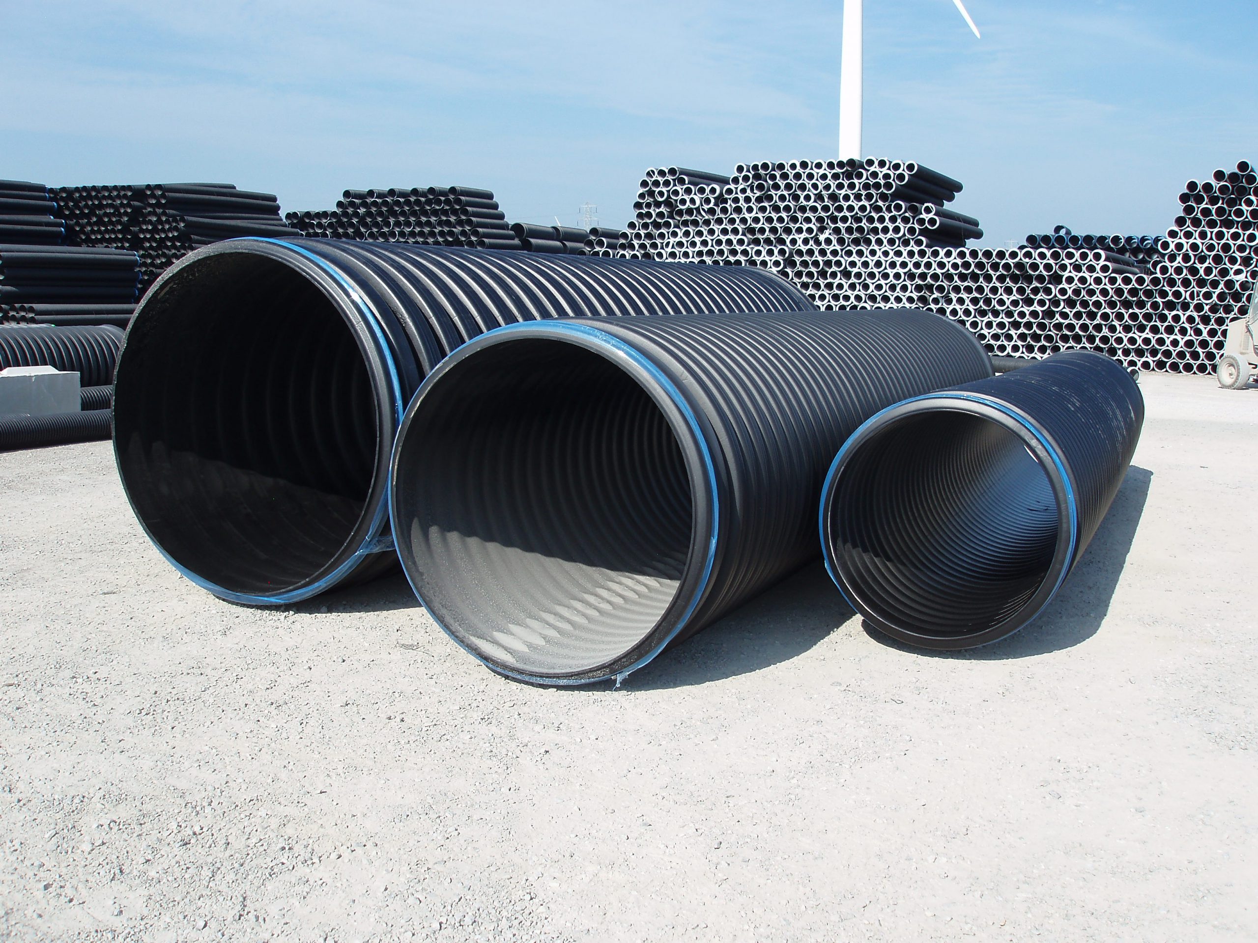
Figure 3: HDPE Pipe (courtesy of Haviland Drainage Products)
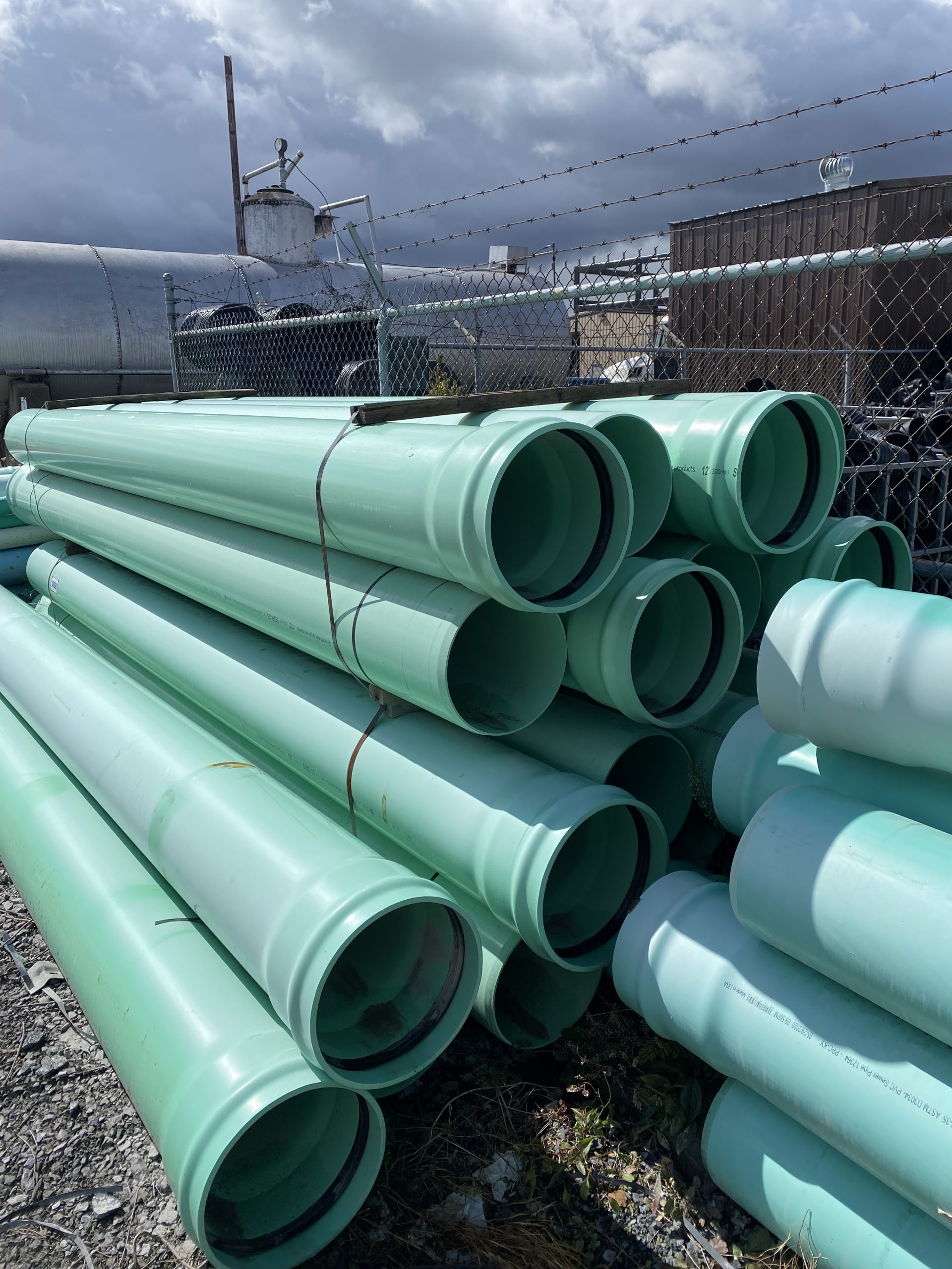
Figure 5: PVC Pipe (courtesy of Haviland Drainage Products)
1.1 Reinforced Concrete Pipe
RCP is a steel-reinforced precast concrete structure that is available in three D-Load strength limit ratings:
- Class III RCP is rated to 1,350 lb/ft/ft (pounds per linear foot per foot of inside diameter).
- Class IV RCP is rated to 2,000 lb/ft/ft.
- Class V RCP is rated to 3,000 lb/ft/ft
1.2 Corrugated Metal Pipe
CMPs are characterized by the base material type used to manufacture the pipe, corrugation type, corrugation depth, corrugation pitch, and the thickness of the sheet stock used to manufacture the pipe. Two base materials are used for CMP — steel (CSP) and aluminum (CAP). Corrugation can be annular, helical, or spiral:
- Annular corrugations are concentric through the length of pipe. The pipe is manufactured with longitudinal seam that is riveted or spot welded. Annular corrugated pipes are rarely used.
- Helically corrugated pipe (shown in Figure 6) is manufactured with a continuous lock seam that runs helically down the longitudinal axis of the pipe.
- A spiral ribbed pipe (SRP, shown in Figure 7) has a smooth interior and a box-shaped rib on the outside. It is manufactured with a continuous lock seam that spirals down the longitudinal axis of the pipe.
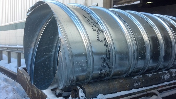
Figure 7:Spiral Ribbed Pipe (courtesy of St. Regis Culvert)
The numbers describe the dimensions of CMP: the first is the pitch or the center-to-center distance between the ribs, and the second is the depth of the rib. Available corrugation patterns are as follows:
- Annular and helical CSPs and CAPs— 2 2/3” x 1/2”, and 3” x 1”
- CAP — 6” x 1” corrugation pattern (used for larger pipe diameters in deeper fill situations)
- CSP — 5” x 1” corrugation pattern (used for larger pipe diameters in deeper fill situations)
- SRP — ¾” x ¾” x 7 ½”. The first two measurements are the dimensions of the boxed rib, and the final dimension is the center-to-center distance between the ribs.
CMP is available in sheet thicknesses from 16 to 8 gage. The lower the gage, the thicker the sheet stock. Protective coatings used for CSP are galvanized aluminized type 2, and polymeric. Each coating provides different levels of protection against abrasion, corrosion, and erosion.
1.3 Thermoplastic Pipe
THP is available in HDPE or PP. Pipes manufactured with HDPE or PP are dual-walled pipes with a smooth interior and a corrugated exterior. PVC pipe is rarely used. It is manufactured as either a solid wall pipe with a smooth interior wall and exterior ribs or a dual wall pipe with a smooth interior wall and corrugated exterior wall. The former is only used for 12” and 15” storm sewer or culvert pipes.
Culvert and storm sewer pipes are categorized as rigid or flexible. A rigid pipe provides most of the strength to carry the earth and live loads, while a flexible pipe relies on the soil envelope around the pipe to adequately support loads. Existing soil conditions can affect the performance of both types, so it is critical that the pipe bed is properly prepared. While flexible and rigid pipes need to be monitored to ensure they perform as intended, flexible pipe installation should be closely monitored, as backfill provides a large portion of the structural integrity.
2.1 Allowable Cover Heights
Contractors may use any type of pipe material in the current Standard Drawings RDI001 thru RDI012 (Type drawing # into table. Do not include any dashes or spaces). Allowable types of pipe material are governed by pipe size and the min/max allowable cover height. Cover height is defined as the dimension from the outside crown of the pipe to the top of subgrade. Generally, the minimum cover height for culverts and storm sewer pipes is 2 feet. Under special circumstances, if the cover height is less than 2 feet, pipe selection is based on a fill height of 30 ft. THPs (HDPE, PP, or PVC) cannot be used if the cover height is less than 2 feet. During construction, the minimum cover height for construction loading is 4-feet. This applies to all pipe materials.
2.2 Types of Protection
Three coating options are available for CSPs — galvanized, aluminized type 2, and polymeric. Coatings are applied to the sheet stock before the pipe is formed. Additional protection is required depending on the base pipe material, the structure’s intended use, soil and water pH, and resistivity of the soil in which the pipe will be installed.
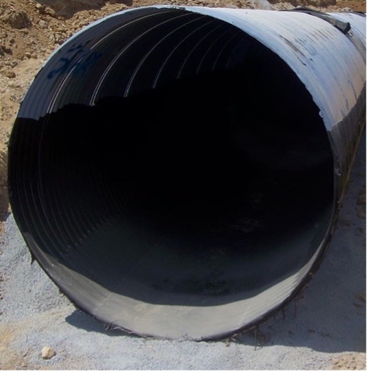
The other form of protection applied to CMPs is bituminous lining (shown in Figure 8). Bituminous lining is applied by dipping the finished pipe into a vat of hot bitumen, lifting it out, and allowing the bitumen to set. Types of bituminous linings include half-asphalt coated, fully asphalt coated, and paved invert. Environmental conditions (pH and soil resistivity) and use type dictate the type of pipe material to be used and what type of lining is required for a pipe. If the pipe is used for a storm sewer, some lining, coating, and paving requirements are waived depending on size and corrugation type. All CAPs require some form of extra protection depending on environmental conditions.
RCPs require extra protection. This requirement increases the minimal wall thickness and is contingent on the environmental conditions of the location where the pipe will be installed.
.
- Width
Determine proper trench width per the following:
Width = Pipe Diameter + 24” for pipes 36 inches or less
Width = Pipe Diameter + 48” for pipe greater than 36 inches
- Depth
Trench depth is determined based on the specified flowline elevation, pipe wall width, and depth of backfill.
If rock foundation is encountered, the trench must be over excavated below pipe invert.
- Reinforced Concrete Pipe
Additional depth limits: minimum of 6” not to exceed 24”
Additional depth = pipe diameter/12
- Flexible Pipe
Additional depth limits: minimum of 4” not to exceed 24”
Additional Depth = 0.042 x height of cover -0.25’
Adhere to the following Standard Drawings for installation:
- Flexible Pipes (Metal, HDPE, etc.)
RDI-025-06 – Trench Conditions
RDI-020-10 – Embankment Conditions
- Reinforced Concrete Pipe
RDI-025-06 – Trench Conditions
RDI-021-10 – Embankment Conditions
- Backfill Materials – Standard Specification 701.02.05
Table A: Granular Backfill
| Pipe Type | Granular Backfill | Notes |
|---|---|---|
| Reinforced concrete | Use size No. 2, 23, 3, 357, 4, 467, 5, 57, 67, 68, 78, 8, or 9M aggregate, or Material conforming to AASHTO M 145 Al or A3 material specifications with a maximum plasticity index of 10 (see Table B below) | Limit rock fragments to a maximum size of 3 inches. |
| Corrugated Metal | Use size No. 2, 23, 3, 357, 4, 467, 5, 57, 67, 68, 78, 8, or 9M aggregate, or Material that conforms to AASHTO M 145 Al or A3 material specifications with a maximum plasticity index of 10 (see Table B below) | Limit rock fragments to a size that does not exceed the corrugation width. |
| Thermoplastic | Use size No. 5, 57, 67, 68, 78, 8, or 9M aggregate, or Material conforming to AASHTO M 145 Al or A3 material specifications | Limit rock fragments to a maximum size of 1.5 inches. For corrugated pipe, limit rock fragments to a size that does not exceed the corrugation width or 1.5 inches, whichever is least. |
| Structural Plate | Use Structure Granular Backfill conforming to Section 805 |
Use size No. 2, 23, 3, 357, 4, 467, 5, 57, 67, 68, 78, 8, or 9M aggregate, or Material conforming to AASHTO M 145 Al or A3 material specifications with a maximum plasticity index of 10 (see Table B below)
Table B: Flowable Fill Conforming to Subsection 601.03.03 B
| Characteristics | A1 | A3 |
|---|---|---|
| Sieve Analysis: Percent passing No. 10 | ---- | ---- |
| Sieve Analysis: Percent passing No. 40 | 50 max | 51 min |
| Sieve Analysis: Percent passing No. 200 | 25 max | 10 max |
| Plasticity index of material passing No. 40 | 8 max | ---- |
*For a complete description see AASHTO M 145
- Backfill
- Acceptable materials
- The contractor must locate a suitable backfill source for each project. If the backfill contains soils, an AASHTO-accredited lab must certify the material conforms to the specified granular material.
- Granular backfill, flowable fill, or embankment material may be used for the backfill of RCP when the pipe is not within one pipe diameter of the subgrade.
- Granular backfill or flowable fill may be used for the backfill for CMP, THP, and structural plate pipe when the pipe is not within one pipe diameter of the subgrade.
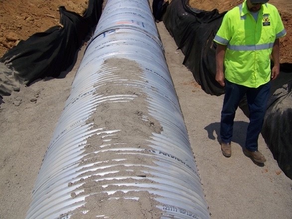
- When pipe is within one pipe diameter of the subgrade, backfill using flowable fill (shown in Figure 9) to an elevation one foot above the pipe in the area within the outside shoulder or back of curb to outside shoulder or back of curb. When installing pipe under existing pavement, backfill with flowable fill to the subgrade elevation.
- Acceptable materials
- Placement and Compaction
- Backfill (shown in Figure 10) must be placed as specified in the contract.
- Backfill should be placed in 6-inch lifts and compacted to a minimum of 95 percent of the maximum density as determined according to Kentucky Methods 64-511.
- Backfill material (granular, flowable fill, or embankment) should be placed to an elevation one foot above the pipe.
- If granular backfill is used and (a) the surrounding conditions are not similar in gradation and (b) the area is that extends from the centerline to 25 feet outside the shoulder or back of curb, bedding and granular backfill must be wrapped in geotextile fabric.
- Construction Loads
Do not allow construction equipment or traffic to travel over the top of structure material until the fill is compacted to a minimum depth of 48 inches over the top of the structure. The Engineer may require temporary cover where the final grade is less than 48 inches. The Engineer may raise but will not lower the minimum cover based on the pipe manufacturer’s recommendations.
- Inspection before installation
-
- Before the contractor begins pipe installation operations, the inspector should verify they have the correct materials and understand the correct installation procedure. Frequently, pipe installations impact the traveling public. Once work begins it is important to complete the installation quickly. The inspector serves as a last line of defense because problems arise if an issue is not identified until after work begins.
- The contractor should designate a “competent person” who is capable of identifying existing and predictable hazards in the surroundings or working conditions which are unsanitary, hazardous or dangerous to workers, and who is authorized to take prompt corrective measures to eliminate them. This is not limited to but should include identifying cave-in risks in trenches, and taking measures such as:
- Sloping and benching the sides of the excavation
- Supporting the sides of the excavation or placing a shield between the side of the excavation and the work area (i.e., trench box, engineered shoring plan, etc.)
- A pipe should have the appropriate certification upon delivery. The contractor should provide a copy of the manufacturer’s handling and installation procedures. When a pipe is delivered it should be inspected for damage or deformities. Issues to look for during inspection depend on pipe type and include:
Concrete pipe:
-
-
-
- Damage to the bell or spigot
- Spalling
- Excessive voids in the walls due to lack of consolidation
- Large gouges or holes in walls
-
-
Metal pipe:
-
-
-
- The pipe is straight and not bent
- The appropriate coating has been applied and is not damaged, missing in areas, or cracked
- The ends are not bent to prevent the band from installing properly
- Holes in the pipe
-
-
Plastic pipe:
-
-
-
- Pipe should be straight
- Pipe should be circular
- No holes or damage to the walls
-
-
- Bedding preparation
- Once the trench is prepared, confirm the width and excavated elevation are correct. Bedding depth and pipe wall thickness should be considered. Compact the excavated bottom before placing the bedding. Then compact the bedding. Confirm the bedding material conforms to the Standard Specifications. Bedding should be shaped to conform to the pipe invert. If the pipe is concrete, a small area must be shaped to accommodate the bell of the pipe.
- Laying pipe and handling
- Pipe must be supported appropriately as it is placed in the trench to avoid damaging the pipe. Concrete and metal pipe require mechanical means of support. Plastic pipe can be handled manually. Pipe should be laid beginning at the outlet end. Each piece (or stick) of pipe should be backfilled.
- The Engineer should verify the installation location (station and offset), inlet/outlet elevations, and that there is an adequate length of pipe specified. The intent is to confirm the contractor’s work, not for the Department to be responsible for the layout. Any discrepancies should be brought to the contractor’s attention immediately.
- Joints
- Connected pieces (or sticks) of pipe must have soil-tight joints and be wrapped with a geotextile fabric. Different types of pipes have different joint types.
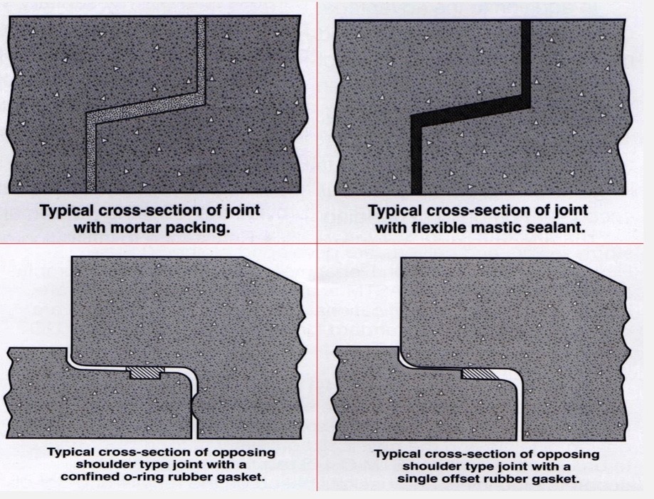
- RCP —Mortar, Asphalt Mastic, Rubber Gaskets, Butyl Rubber Sealants. Tied joints must be used on slopes steeper than 3:1 if the joint is located within 12’ of an outlet per Standard Drawings (see Figures 11 and 12).
- CMP— For pipes up to 54”, the joint is a 12” band. For pipes greater than 54”, the joint is a two-piece 20” band. The band’s gauge may be two gauges lighter than the pipe it is connecting, with a minimum of 16 gauge.
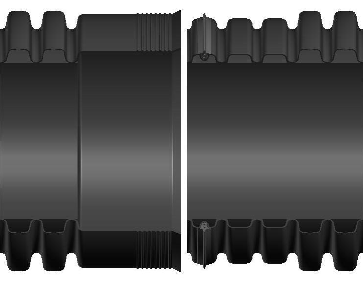
- TMP—An integral bell and spigot joint with elastomeric seal is required. However, if a joint is on a 3:1 or steeper slope or within 12” of an outlet, it must be a cleated integral bell locking joint or standard coupling aided by two #14 2-inch galvanized sheet metal screws per Standard Specifications.
- Connected pieces (or sticks) of pipe must have soil-tight joints and be wrapped with a geotextile fabric. Different types of pipes have different joint types.
- The Engineer must visually inspect all pipe.
- Projects (a) with more than 250 linear feet of storm sewer and/or culvert pipe and (b) located on routes with ADT greater than 1,000 require camera/video inspection.
- The Engineer must be notified at least 24 hours before an inspection.
- Camera/video inspections are performed in accordance with KM 64-114 on 100 percent of pipes located under the road and 50 percent of pipes not under the road.
- Camera/video and laser deflection inspection must be completed by a prequalified contractor certified according to KM 64-114 and prequalified for work types J51 (Video Pipe Inspection and Cleaning) and J87 (Video & Laser Pipeline Inspection).
- The laser method can only be used for deflection testing of pipe up to 48” in diameter. For pipes greater than 48” in diameter, mandrel or physical measuring is used. Concrete pipes do not have to undergo deflection testing.
- Schedule inspections a minimum of 30 days after completing installation and earthwork within 1 foot of the finished subgrade. If final surfacing conflicts with the 30-day minimum, conduct inspections before placing the final surface.
- Standard Specification 701.03.08 contains specific information on the inspection procedure.
- Laser deflection inspection has been halted until further notice. All deflection testing must be done with mandrels. The Special Note for Pipeline Inspection should be in contract documents and outlines the procedure for inspection.
