Search for articles or browse our knowledge portal by topic.
Clear Zone in Workzones
Apply the clear zone concept to all work zones as appropriate for the type of work and to the extent permitted by roadside conditions. Due to the limited horizontal clearance available and the heightened awareness of motorists through work zones, clear zone requirements should be more flexible than those for permanent conditions. KYTC’s Highway Design Manual (HD-206.5) and Chapter 9 of AASHTO’s Roadside Design Guide (RDG) provide specific information for establishing clear zones in work zones.
Use engineering judgment when applying clear zone concepts to work zones. In work zones, whenever feasible, use the following information to establish the clear zone width:
- Traffic speeds and volumes
- Roadway geometrics
- Available right-of-way width
- Cost
- Duration of work
Depending on site restrictions, it may be feasible to provide only an operational clearance.

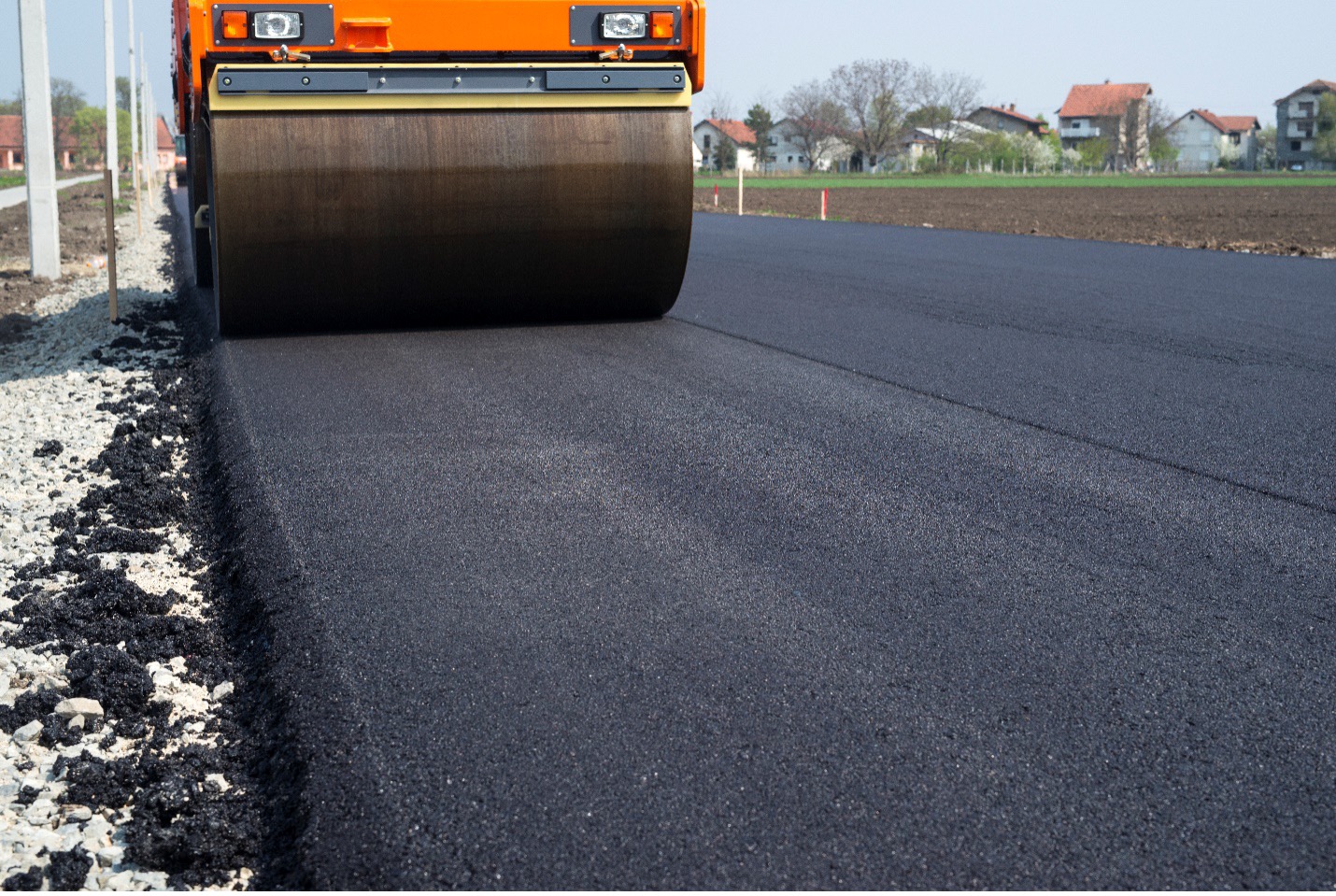
Pavement edge drop-offs may occur during highway work. If not properly addressed, drop-offs may result in an errant vehicle losing control. No vertical drop-off > 2 in should occur between adjacent lanes where traffic is expected to cross in a lane-change maneuver. Place warning signs in advance of the area in accordance with the MUTCD.
Consider the following guidance when contending with pavement edge drop-offs in construction zones:
- < 2 in—No protection required. Note: Place warning signs in advance of and throughout the drop-off area.
- 2 – 4 in—Deploy plastic drums, vertical panels, or barricades every 100 ft on tangent sections for speeds of > 50 mph. Note: Cones may be used in place of plastic drums, vertical panels, or barricades during daylight hours. For tangent sections with speeds < 50 mph and curves, place devices every 50 ft. Follow MUTCD guidance to establish appropriate spacing between devices on tapered sections.
- > 4 in—Positive separation or wedge with 3:1 or flatter slope needed. Note: Place channelizing devices along the traffic side of the drop-off. Maintain, if practical, a 3 ft buffer between the edge of the travel lane and drop-off. If the drop-off is > 12 inches, positive separation is strongly encouraged. If concrete barriers are used, special reflective devices or steady-burn lights should be used for overnight installations.
For temporary conditions, drop-offs > 4 in may be protected with plastic drums, vertical panels, or barricades for short distances during daylight hours while work is performed in the drop-off area.

When construction equipment and/or traffic control devices are not being used, they are to be placed outside the clear zone, beyond the ditch line, behind guardrail, or off existing right-of-way (see KYTC Standard Specification 112.03.03). The Engineer approves locations if they are within the existing right of way and designates specific areas within the right of way where personal vehicles may park.
- HD-800 Roadside Design
- HD-206.5 Roadside Design in Work Zones
- HD 1201.4 Sign Supports
- 03.03 Equipment and Traffic Control Devices Not In Use.
- PE-204 General – Work Zone Safety
AASHTO. Roadside Design Guide, Fourth Edition, RSDG-4. American Association of State Highway and Transportation Officials, Washington, DC, 2011.
AASHTO. Guidelines for Geometric Design of Low-Volume Local Roads, Second Edition. American Association of State Highway and Transportation Officials, Washington, DC, 2019.
Roadside Safety Clear Zone Concepts Knowledge Book:
Access the complete Knowledge Book here: Roadside Safety Knowledge Book (coming soon) and Clear Zone Concepts Knowledge Book
Next Article: Clear Zone for Traffic Appurtenances, Utilities, and Permitted Activities
Previous Article: Enhanced Lateral Offsets for Urban Environments

