Search for articles or browse our knowledge portal by topic.
Rock Slopes and Rockfalls
KYTC and the public incur direct and indirect costs when rock slopes fail. Direct costs include those associated with cleaning up a failure, repairing damaged roadway surfaces, and stabilizing the remaining slope. Indirect costs include personnel time required to engineer a repair, injuries to highway users, vehicle damage, and disrupted traffic. Reducing the probability of a rock slope failure confers important economic, operational, and liability benefits to the Cabinet.
Sedimentary rocks cover about 99% of Kentucky’s surface. Sedimentary rocks form through the accumulation of rocks, shells, plant matter, muds, and sands. Over geological time, these materials were transported by water, wind, or ice and deposited into layers thousands of feet thick, after which they were compacted, hardened, and cemented together under their own weight.
Since most of Kentucky’s sedimentary rocks were deposited underwater, bedrock layers are nearly horizontal except in areas where the movement of the earth’s crust has deformed or tilted them.
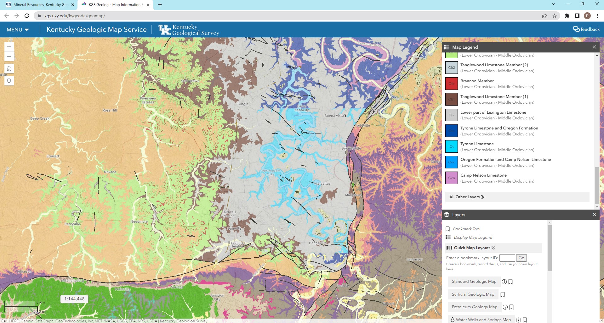
Figure 1. Screenshot of KGS online Geologic Map Service showing the area surrounding Herrington Lake.
2.1. Sedimentary Bedrock
The following sections briefly discuss sedimentary rocks found in Kentucky.
2.1.1. Limestone
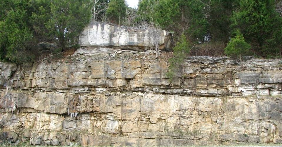
Limestones — which make up more than 50% of Kentucky’s surface bedrock — contain the mineral calcite, are usually layered, and may contain fossils of shellfish and other animals that lived in shallow seas (Figure 2). Limestone fizzes when treated with hydrochloric acid, and natural acids in groundwater can dissolve limestone, creating caves and other karst features.
2.1.2. Sandstone
Sandstones consist of small mineral grains, typically quartz, which have been cemented together (Figure 3). Typically, they are resistant to weathering, although some are easily crushed or eroded (friable). Sandstones are responsible for most of the rugged terrain in eastern Kentucky and are good reservoirs of oil and natural gas.
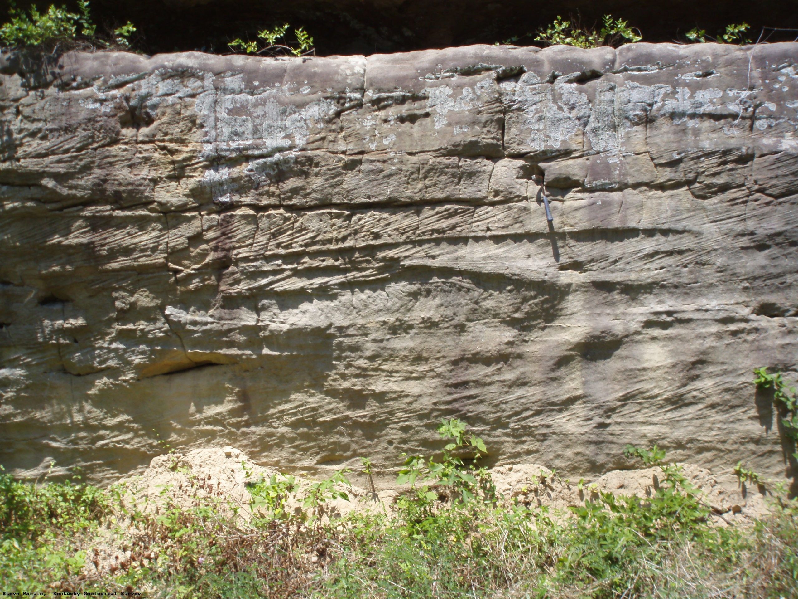
Figure 3. Cross-bedded sandstone of the Lee Formation along KY 7 near MP 12.9 in Elliott County at the Little Sandy River. This sandstone is somewhat friable as indicated by sand accumulated at the base of the cut (photograph courtesy of KGS, Image ID 2320).
2.1.3. Conglomerates
Conglomerates are like sandstones, except they contain larger pebbles, cobbles, and boulders embedded within a sand matrix. Rock fragments are usually composed of quartz and are rounded from having been transported along a stream bed.
2.1.4. Shale
Shales are primarily composed of soft clay minerals. They can appear hard and brittle when dry. Most shales split into thin plates or sheets but can be massive and blocky in some circumstances.
Black shale is the most prominent shale type in Kentucky and is often referred to as Chattanooga, New Albany, or Ohio black shale (Figure 4). It is pyritic, bituminous, carbonaceous, and contains enough organic material to burn. Because black shale contains pyrite, it produces acidic runoff when exposed to oxygen and water (Figure 5). When found in rock cuts or used as fill material, special care must be taken to prevent the development of acidic runoff and associated environmental problems.
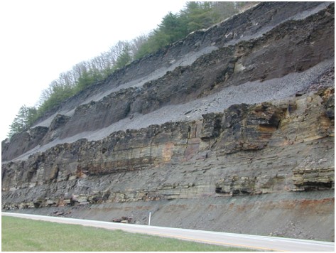
Figure 4. Black Shale
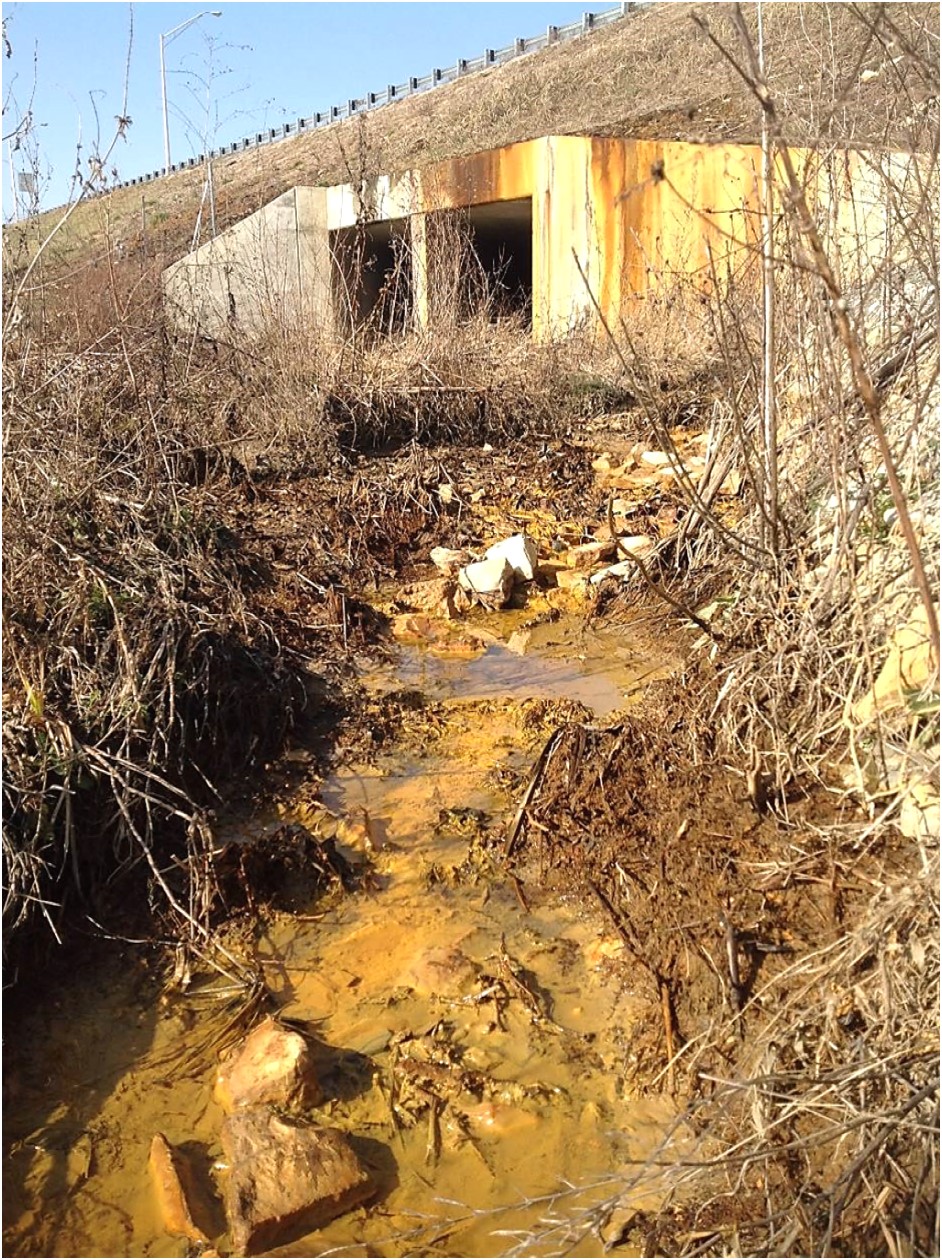
Figure 5. Acidic Runoff
As shales weather, they break down into mud and clay. Their weathering characteristics are measured by the slake durability index (SDI) test. Rocks that weather slowly have a high SDI number. Rocks that weather quickly have a low SDI number. Based on SDI values, shales are classified into durable and nondurable classes.
A simple and quick method to determine whether a shale is durable or nondurable is the Jar Slake Test (Kentucky Method 64-514). To carry out this method, an oven dried sample of rock is submerged in water and observed for 24 hours (Figure 6). Jar slake values are then reported using a visual classification system, with categories ranging from 1 (sample degrades into pile of flakes or mud) to 6 (no change). In the field this method can be adapted by soaking a rock sample in a cup or bucket of water and observing its behavior.
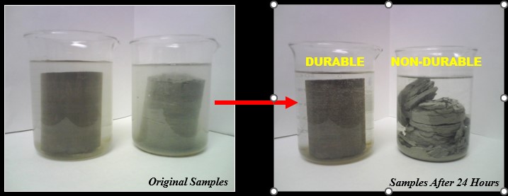
Figure 6. Durable and nondurable shale samples after soaking in water for 24 hours.
2.1.4.1. Durable Shale
Durable shales have SDI values ≥ 95 and generally correlate with a Jar Slake Category of 6. Resistant to weathering, their performance when used in fills is similar to crushed limestone and sandstone.
2.1.4.2. Nondurable Shale
Nondurable shales have SDI values < 95 and are divided into three classes for design purposes only (Table 1). The classification of nondurable shale informs rock cut designs and influences the strength of materials when used as fill. Class I nondurable shales are somewhat resistant to weathering, while Class III nondurable shales weather readily into soil when exposed (Figure 7). Nondurable shales weather into clayey soils, although they may appear to be hard rock when first excavated. Nondurable shales require special compaction techniques when used in fills (Section 206.03.02D of the Standard Specifications, current edition).
| Table 1. Nondurable Shale Classes | ||
|---|---|---|
| Nondurable Shale Class | SDI Range | Jar Slake Category |
| I | 80 to 94 | 4 or 5 |
| II | 50 to 79 | 3 or 4 |
| III | 49 or less | 1 or 2 |
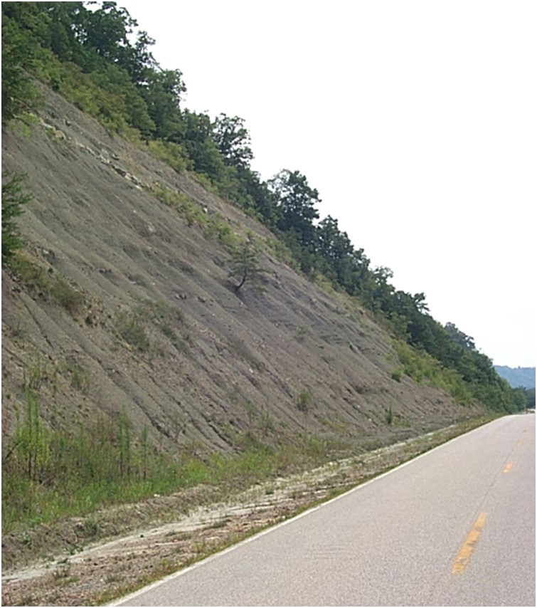
Figure 7. Nondurable shale formation
2.1.5. Coal
Coal is a combustible rock formed by the compaction and alteration of peat (Figure 8). Peats are decayed vegetation typically associated with swamps. Coal occurs in 57 of Kentucky’s 120 counties (37 counties in the Eastern Coal Fields and 20 counties in the Western Coal Fields).
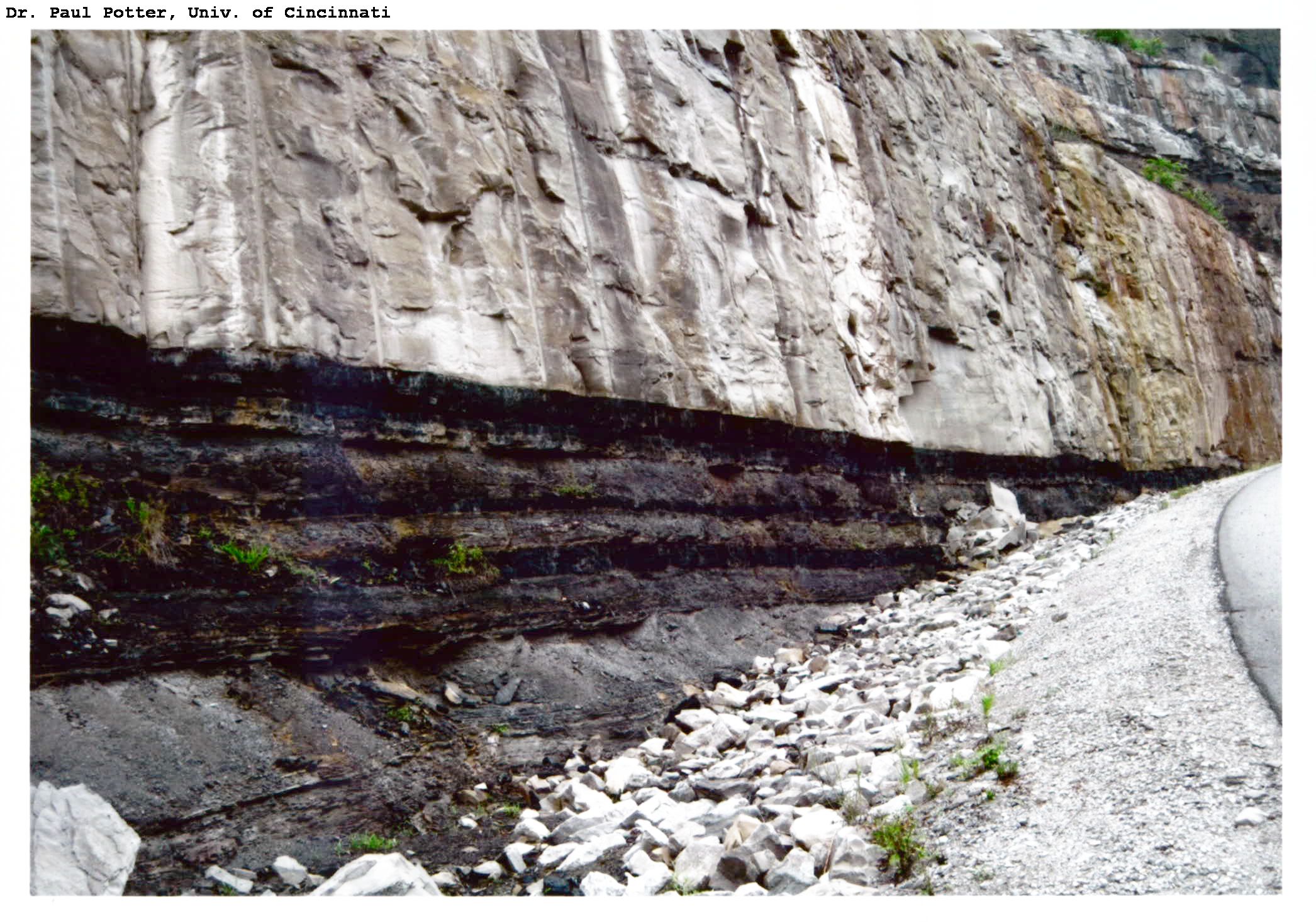
Figure 8. Coal bed in the Pikeville Formation with overlying sandstone along the KY 3220 Connector access road next to US 119 near Sydney, Kentucky (photograph courtesy of KGS, Image ID 3228).
2.1.6. Interbedded Rocks
Interbedding occurs where layers of rocks with different lithological properties alternate with one another. An example of interbedding would be a layer of shale sandwiched between layers of limestone. Limestones, sandstones, and shales are commonly interbedded (Figure 9). Limestones with notable proportions of shale may be described as argillaceous (contains clay).
Interbedded materials present challenges because distinct layers within formations have different weathering and performance characteristics. The differing weathering characteristics produce distorted SDI values that do not accurately represent the behavior of bedrock.
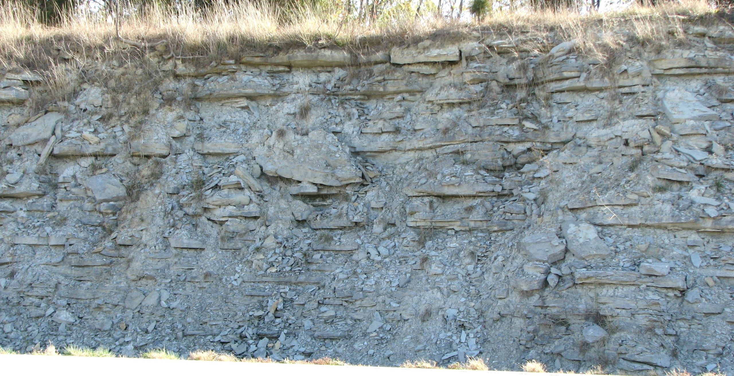
Figure 9. Interbedded limestone and shale of the Clays Ferry Formation along I-64 near MP 99.6 in Clark County, Kentucky (photograph courtesy of KGS, Image ID 3542).
2.2. Structural Features
This section reviews common geologic terms. A more extensive list of terms can be found online at Geology.com or on the National Park Service Geology page.
2.2.1. Bedding Planes
Bedding planes are boundaries that separate rock layers and are caused by depositional layering or the stratification of sediments (Figures 10 and 11).
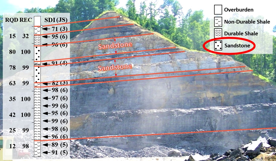
Figure 10. Newly constructed rock cut showing different rock types and bedding planes as compared to the rock core taken during the design of the rock cut.
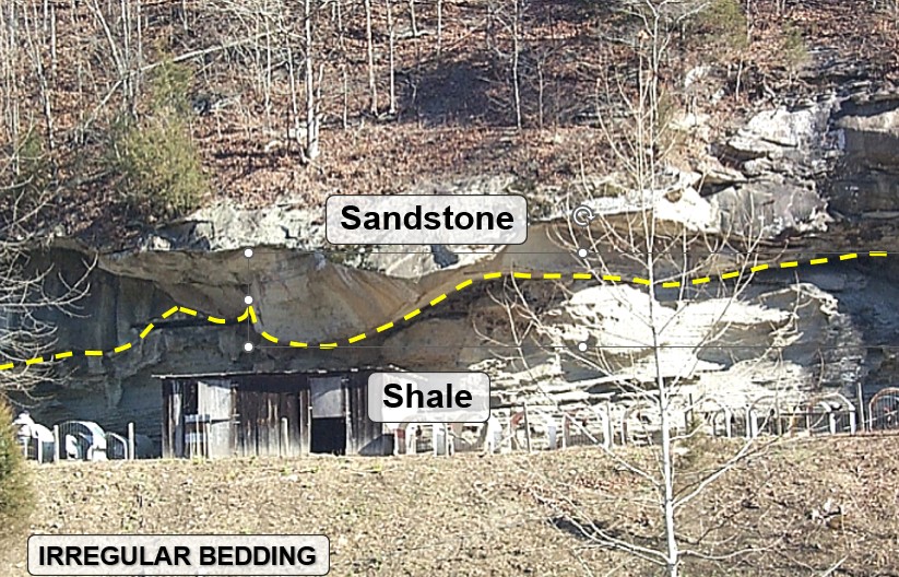
Figure 11. Irregular bedding plane due to erosion of the underlying shale prior to deposition of the sandstone.
2.2.2. Joints
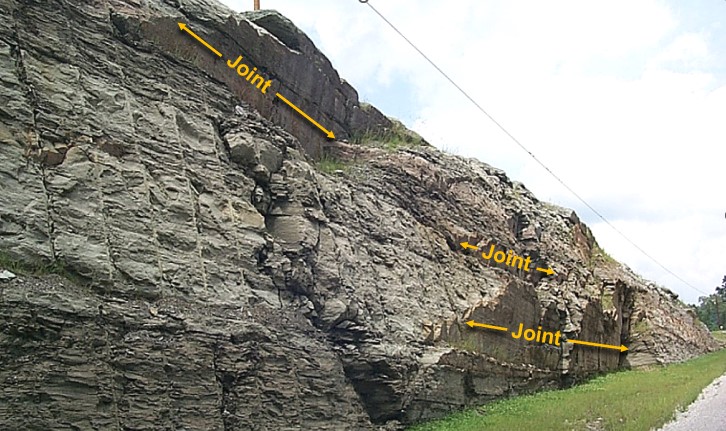
Joints are cracks in rock without relative movement on either side of the crack (Figure 12). They are typically caused by shrinkage or the release of pressure as rocks above erode away. They commonly occur in a plane and can occur in parallel and/or intersecting sets.
2.2.3. Faults
Faults are deep cracks created when rock movements occur during earthquakes (Figure 13). Different or displaced rock formations are visible on each side of a fault.
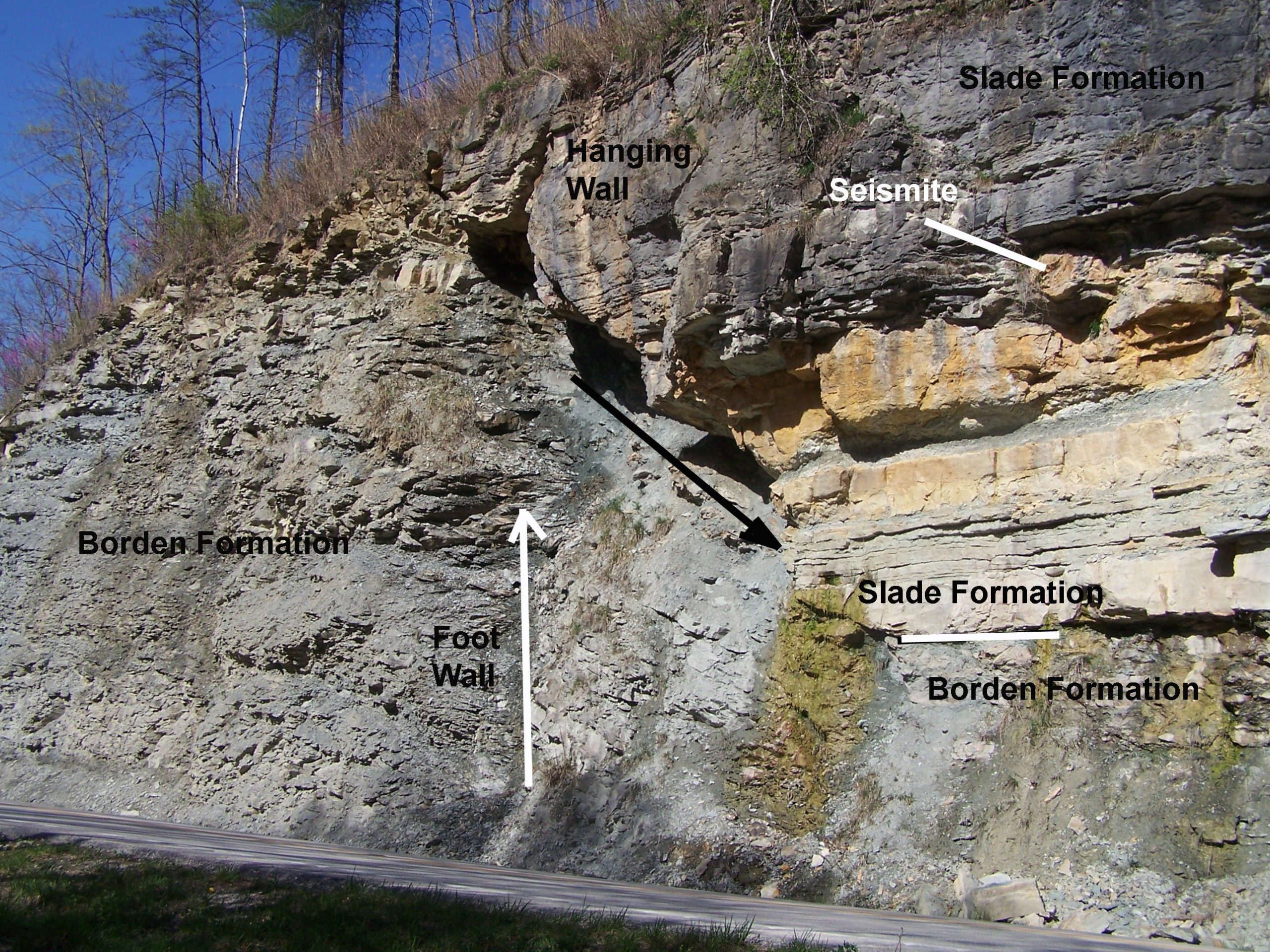
Figure 13. Glencairn Fault along KY 11 near MP 4.8 in Wolfe County, KY (Photograph courtesy of KGS, Image ID 3772).
2.2.4. Dip and Strike
Dip is the angle of a bedding plane or other surface (e.g., a joint) relative to the horizontal plane (Figures 14 and 15). Strike is the compass direction of the line of intersection of an inclined surface (e.g., a dipping bedding plane or joint) with a horizontal plane.
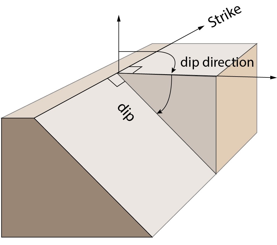
Figure 14. Relationship between dip and strike
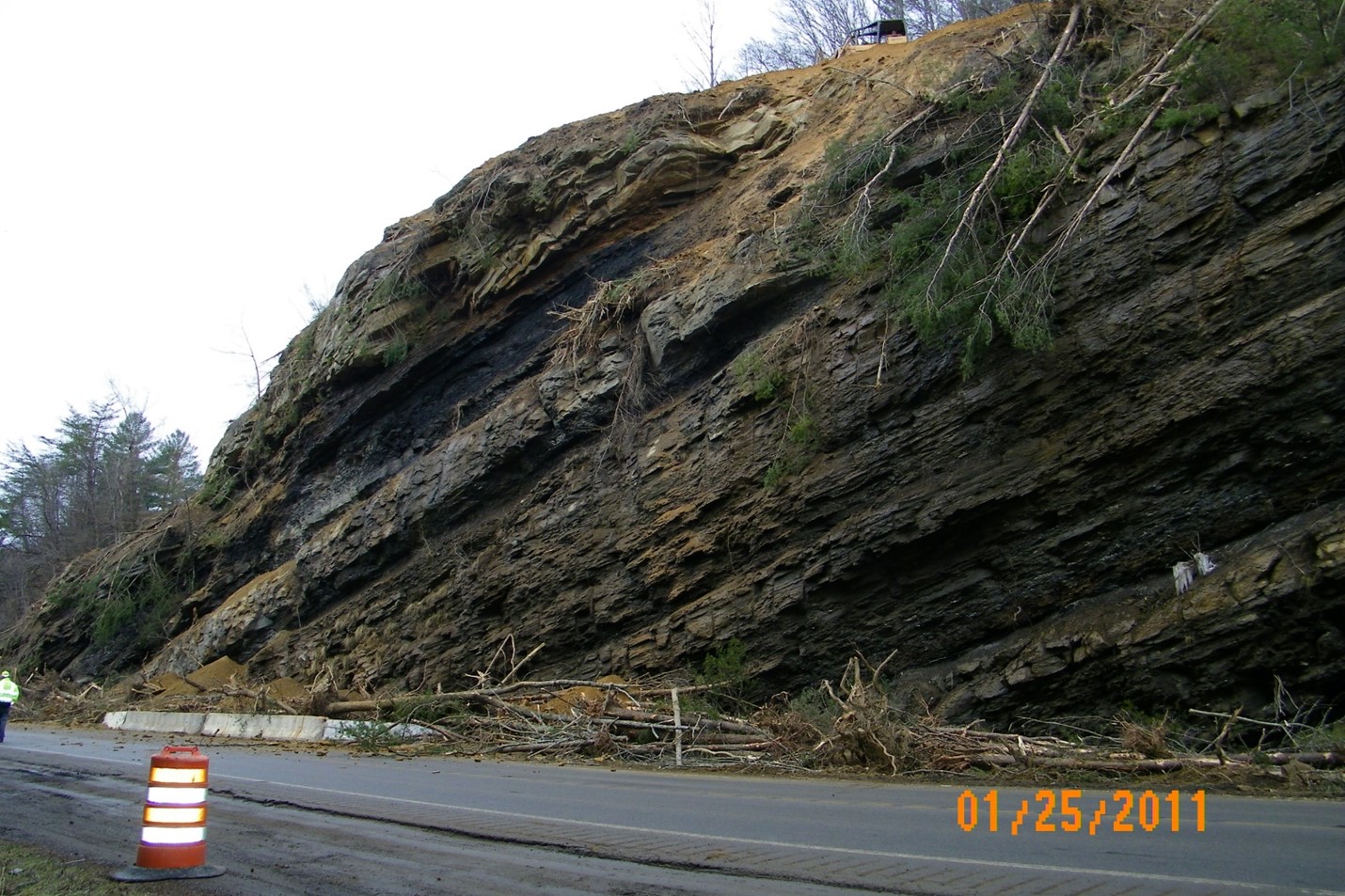
3.1. Falls
Falls are rapid, free-falls of rock from steep slopes or cliffs (Figure 16). A falling mass can break when it impacts the bottom of the slope, or it can bounce or roll. The volume of material that falls ranges from individual rocks and boulders to massive blocks of bedrock thousands of cubic feet in volume. Falls typically occur due to a slope being undercut by weathering, erosion, or human activities (e.g., excavation).
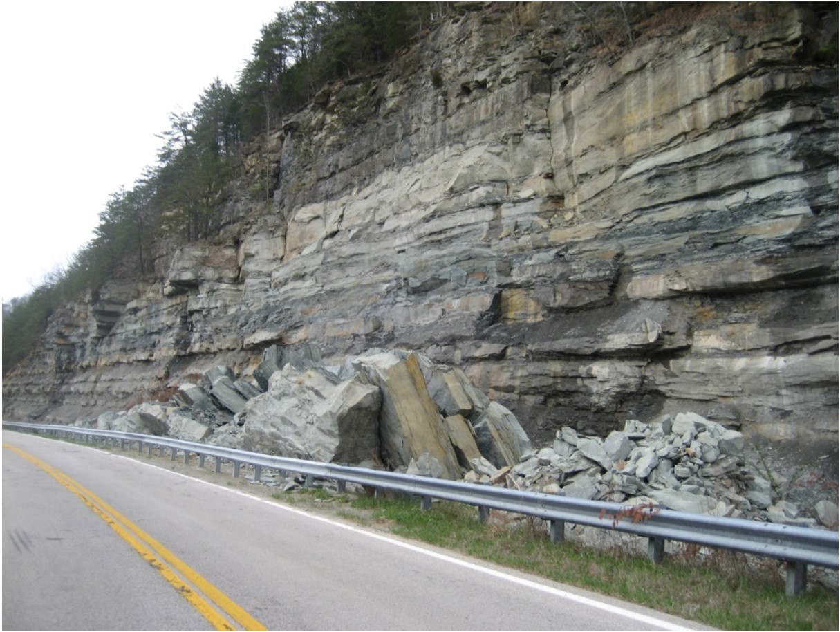
Figure 16. Rockfall
3.2. Topples
Topples occur when a mass of rock rotates forward around a pivot point that is located below the mass’s center of gravity (Figure 17). Topples are usually driven by gravity but can be triggered by water or ice in the cracks of bedrock. Weathering, erosion, and human activities can also contribute to topples. Topples may occur slowly or rapidly, but their impacts can be extremely destructive.
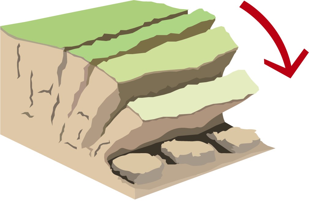
Figure 17. Rock Topple
3.3. Slides
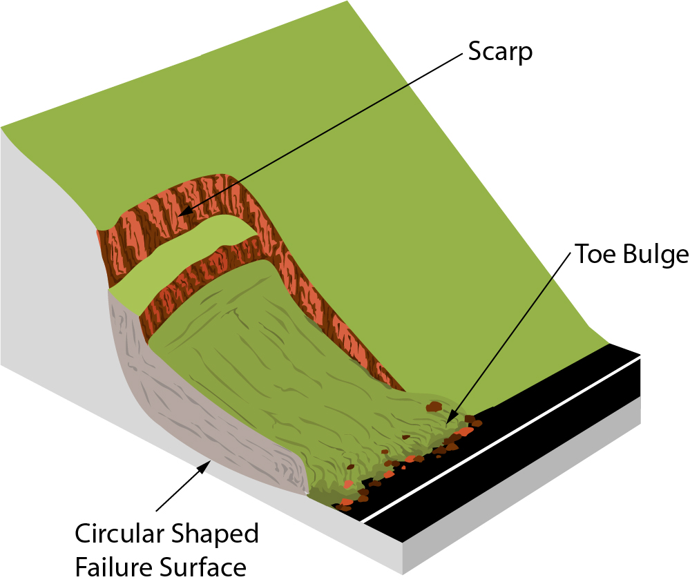
Figure 18. Rotational Slide
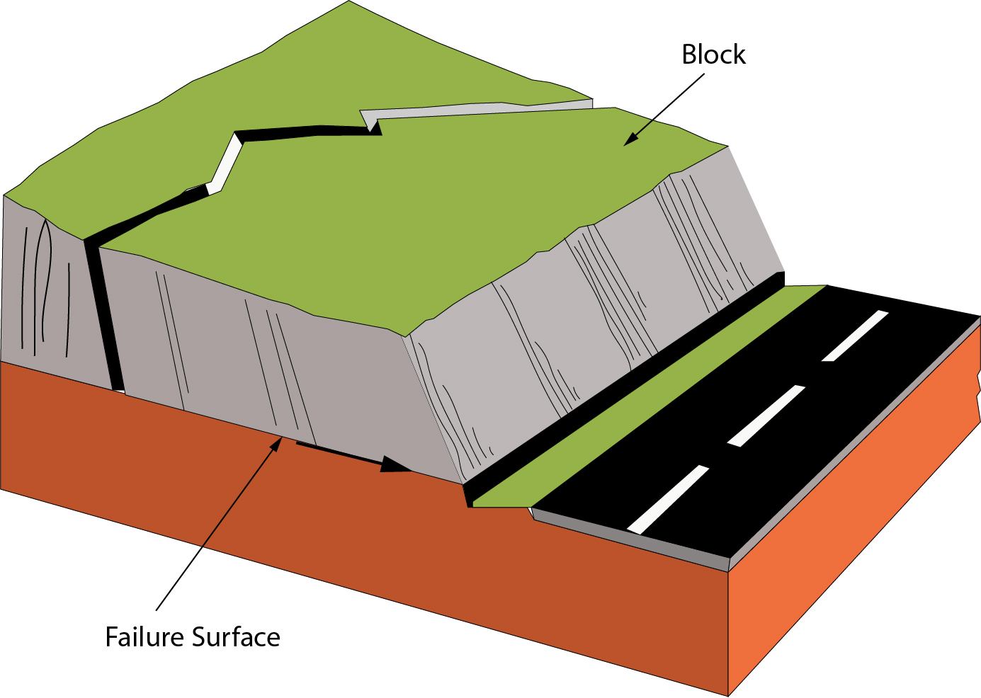
Figure 19. Translational Slide
Slide movement may be slow initially but can accelerate as the slide progresses. Slides that occur in bedrock range in size from small to millions of cubic feet of displaced material. Small slides may require only minor cleanups, while massive slides potentially have consequential impacts (e.g., damming of rivers that results in flooding).
3.4. Contributing Factors
3.4.1. Water
Water is an underlying cause of many slides and rockfalls. Precipitation, fluctuations in nearby river or lake levels, and erosion influence the frequency and intensity of slides and rockfalls. Water saturates the soil and rock mass, which adds to its weight and reduces the material’s ability to resist movement (i.e., reduces its strength). Freeze-thaw cycles can widen joints and cracks in bedrock and increase the pressure placed on them.
3.4.2. Differential Weathering
Some types of bedrock that deteriorate and weather rapidly can undercut more resistant bedrock. Shale, for example, weathers more quickly than limestone and sandstone, which means it can undercut layers of less resistant rocks (Figure 20).
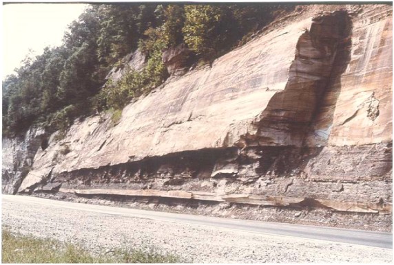
3.4.3. Joints
Water held in bedrock joints increases pressure within the rock and can trigger a fall or slide. The water can also freeze and widen the joint or push out a block of rock.
A joint’s angle or dip influences the potential for rock falls or slides. When cut slopes are steeper than the joint angles in bedrock, opportunities arise for a block of bedrock to fall or slide out of a slope (Figures 21 and 22).
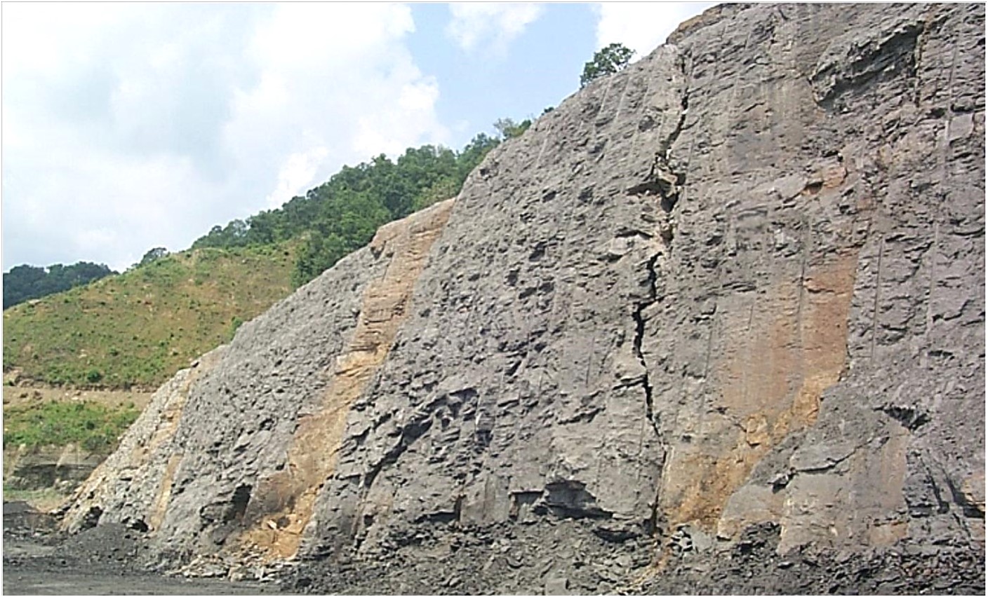
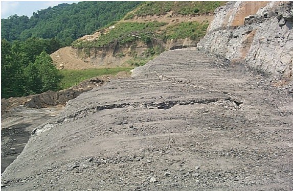
Figure 22. View of wedge failure from the top showing cracks in the rock bench.
3.4.4. Bedding Planes
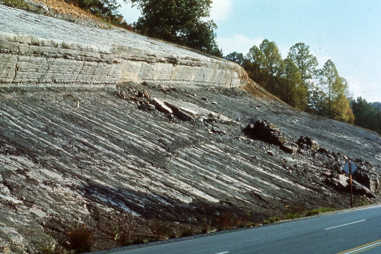
Bedding planes occur where different layers of bedrock meet. Typically characterized as weak planes, they frequently separate different types of bedrock that vary in their composition and strength. Where bedding planes dip and more resistant bedrock types (e.g., limestone, sandstone) overlie a weaker shale layer, the potential for large translational slides exists (Figure 23).
3.4.5. Karst Terrain
Common throughout Kentucky in areas underlain by limestone, karst terrain is characterized by sinkholes, caves, sinking streams, springs, and underground drainage. Weak acids naturally found in rain, snow, and soil slowly dissolve limestone and create karst features.
Rock cuts with karst features are more vulnerable to rockfalls because rocklines are irregular and bedrock structures are weakened. Irregularities create problems with the overlying soil slopes, resulting in landslides or encroachment beyond right-of-way limits (Figure 24). When encountered in a rock cut, cave roofs can collapse and trigger rockfalls (Figure 25).
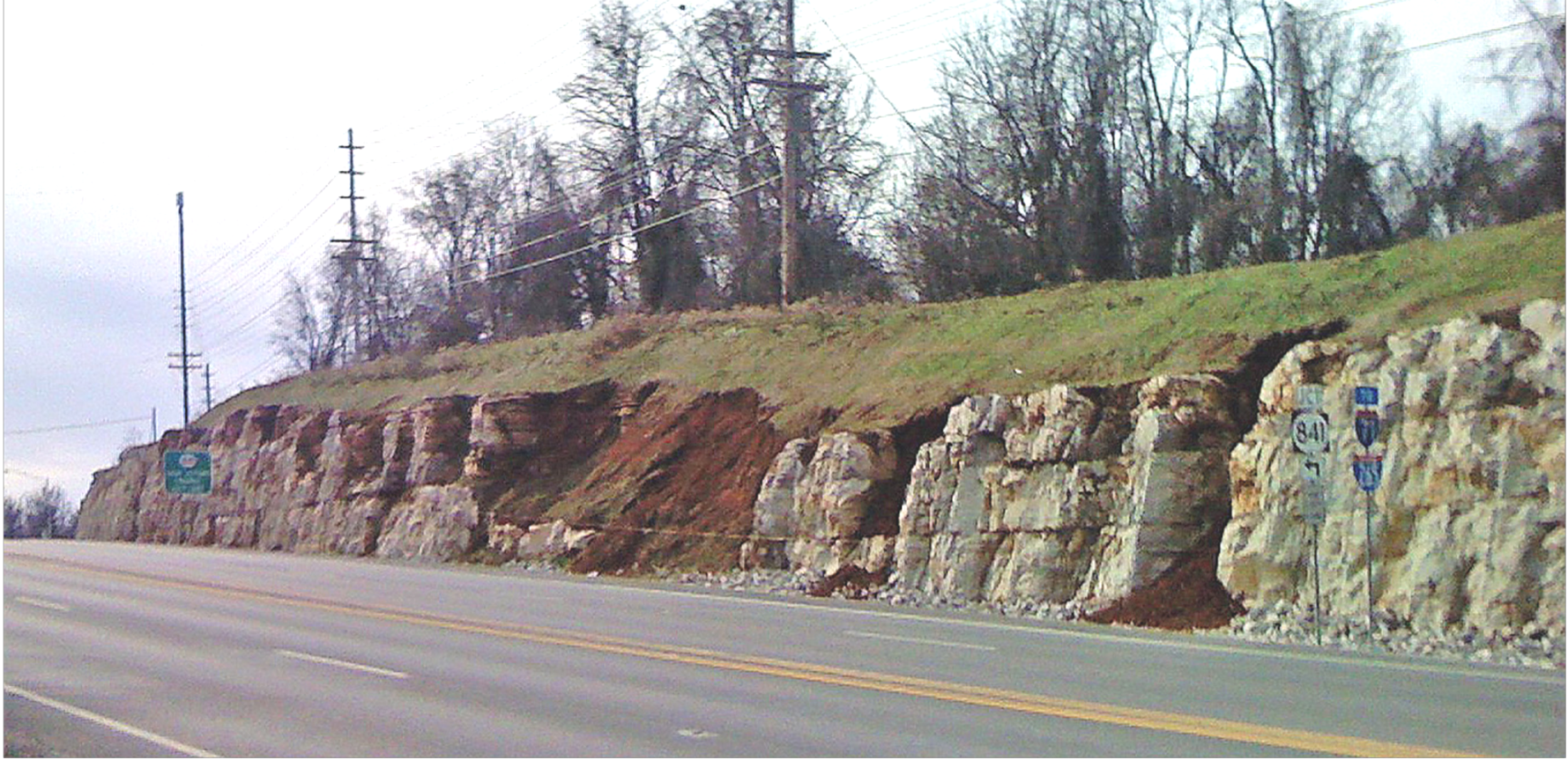
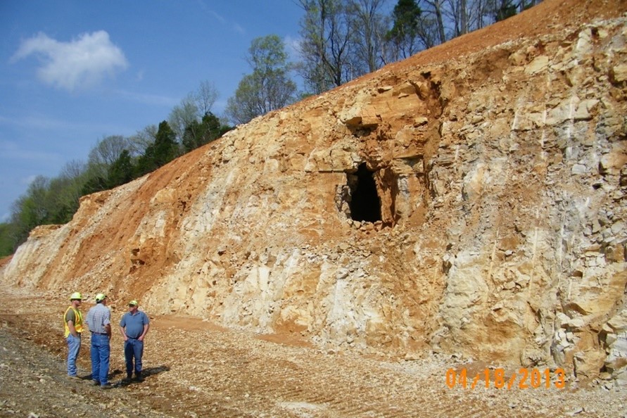
Figure 25. Cave encountered in a newly constructed rock cut during construction.
3.4.6. Human Activities
Human activities that can trigger slides and rock falls include the excavation of a slope or its toe, loading the slope at the top, removing vegetation, mining activities, blasting, and diversion of water.
Monitoring rock slope movements is important for their maintenance, preventing rock falls and their effects, and determining corrective measures for problematic rock slopes.
4.1. Visual
Visual inspections are the most common method of monitoring rock slopes. Inspectors look for the following indicators to locate areas where slopes are failing or may be prone to failure:
· Weathering or erosion of rock formations
· Changes in joint widths
· Rock fall material at the base of the slope
· Rock fall impact indications in driving surfaces
· Surface and groundwater changes
· Surface cracks
· Vegetation changes
· Tilted trees or power poles
Other methods can supplement visual inspections, including surveying reference points. Visual inspections should be documented through photographs.
4.2. Instrumentation
On rock slopes where the effects of a rock fall may have significant impacts, installing instrumentation to measure slope movement or changes may be practical. Commonly used instruments include:
· Extensometers to measure crack width changes
· Automated surveying techniques to measure changes in the rock surface
· Tiltmeters to measure rotation
· Inclinometers to measure locations of slope movement and rate
Instrumentation can be monitored remotely. Alarm devices can be installed to warn transportation personnel or the public if the slope movement exceeds a pre-determined threshold.
4.3. Remote Sensing
Remote sensing using Lidar, satellite data, photogrammetry, drones, and other methods of obtaining three-dimensional data sets of slope surfaces can be used to document and quantify slope changes. Computer software is used to compare datasets and delineate changes in surfaces over time. This information can help identify areas that may need to be stabilized or where protective measures can help prevent or contain a rock fall.
On some roadways, maintenance is needed to control rock falls or problems with rock slopes. Stabilization measures should be chosen based on site conditions. Inappropriate stabilization measures may worsen rock falls or slope instability. Contact the Geotechnical Services and the Engineering Geology and Field Services Branches of the Division of Structural Design to evaluate, recommend, design, and implement the most appropriate stabilization measures for each site.
5.1. Rock Removal
5.1.1. Scaling and Trimming
Scaling and trimming removes loose, overhanging, or protruding rock on the face of the slope that can dislodge and fall or affect the trajectory of falling rock. This is done by hand using scaling bars, by small equipment such as excavators, or by light explosives. Trained maintenance personnel can scale slopes, but there are contractors that specialize in this service.
5.1.2. Re-sloping – Excavation, Benching, and Reshaping
Re-sloping involves modifying a rock slope to establish proper slope angles, benches, and catchment areas at the toe. More right of way may be needed when re-sloping is used. Typically, KYTC contracts out this work because modifying rock slopes usually involves blasting and excavating fairly large quantities of earth.
5.2. Reinforcement
Reinforcement anchors a block against potential movement or provides a resisting force to sliding along a planar surface.
5.2.1. Bolting and Dowels
Rock bolts and dowels are drilled through a block into a more stable layer. Bolts can be tensioned or un-tensioned (Figure 26):
· Tensioned bolts anchor a block and increase friction between a block and underlying stable layer.
· Un-tensioned bolts provide resistance against a block sliding through the bolt’s shearing, but it can also prevent some rotational movement of a block.
Dowels typically only provide resistance against sliding through shearing of the dowel. Bolts and dowels can be grouted if needed.
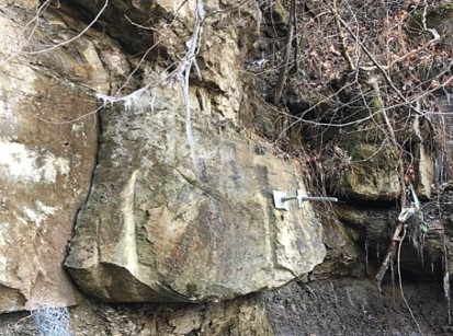
Figure 26. Rock bolts
5.2.2. Shotcrete
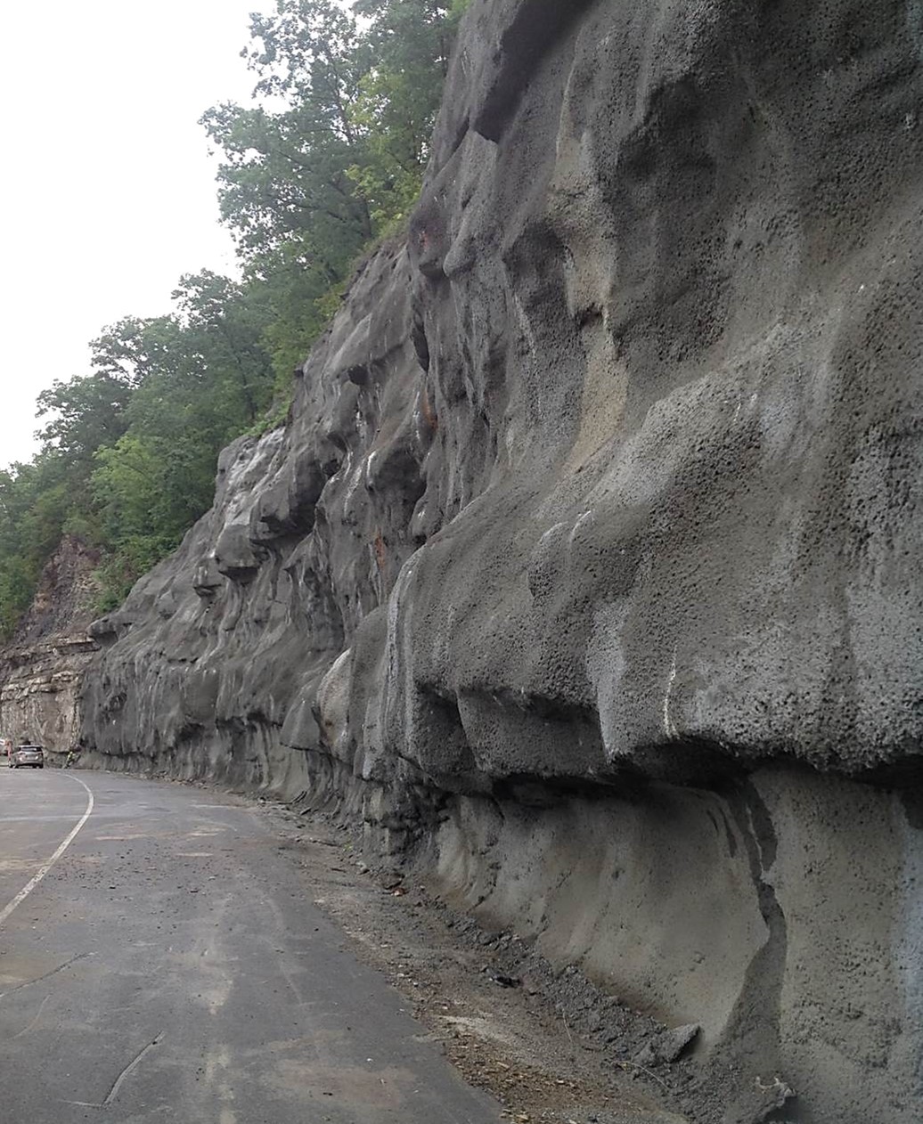
Figure 27. Shotcrete applied to rock cut along KY 1420 in Pikeville, KY.
5.2.3. Injection
Resin or epoxy injected into drilled boreholes follows fractures and discontinuities to bond blocks of rock with one another. Injection is often used in conjunction with rock bolts.
5.2.4. Backstowing
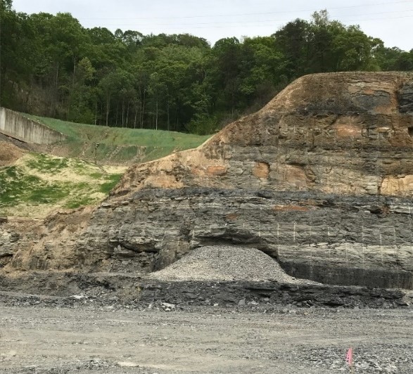
Figure 28. Backstowed mine opening
5.2.5. Buttresses and Retaining Walls
Concrete buttresses and retaining walls support rock overhangs or provide additional resisting forces against the sliding of a block of material (Figure 29). They must be designed to support the weight of material or resist the driving forces of a sliding block. They can be anchored into stable underlying materials to provide additional sliding resistance.
Retaining walls are usually made of concrete, but other types of walls (e.g., gabions, mechanically stabilized earth, geosynthetically confined soil) can be used if properly designed and constructed.
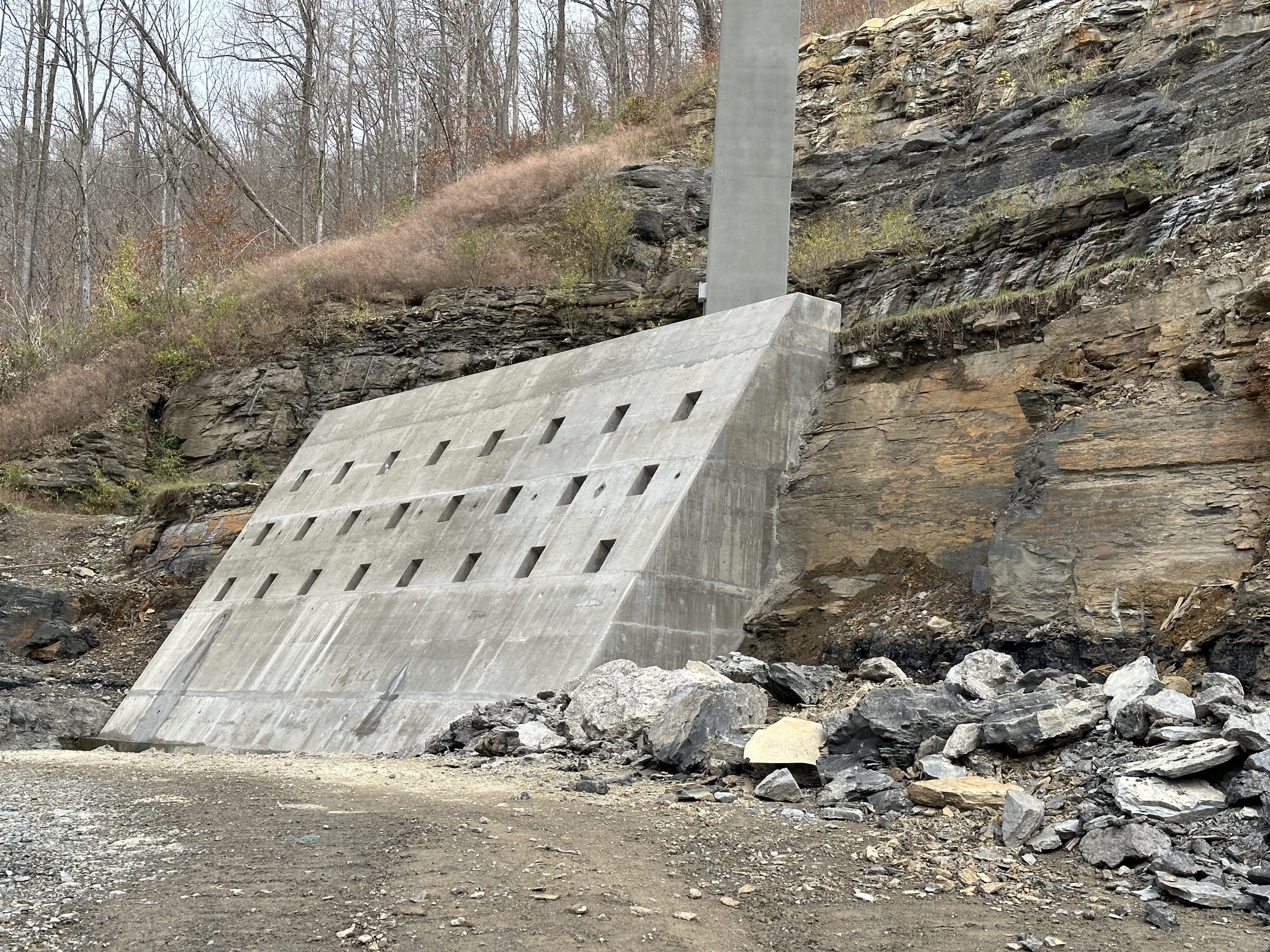
Figure 29. Concrete buttress with rock anchors to help support a rock cut below a bridge pier on US 460 in Pike County, Kentucky (photograph courtesy of John Michael Johnson, KYTC District 12).
5.3. Drainage
Proper surface and subsurface drainage can slow down the deterioration of and stabilize a slope. Surface drainage features can direct water flowing downslope away from fractures and reduce the erosion of susceptible bedrock. Subsurface drains (e.g., horizontal drains) can be drilled into a slope to help drain groundwater.
5.4. Protection Measures
Sometimes it is cost-effective to let rock falls occur but control the distance and direction in which they travel. This involves building protective structures that absorb the rockfall’s energy.
5.4.1. Catch Ditches
Catch ditches can be a cost-effective measure if sufficient space exists at the slope’s toe (Figure 30). The required depth and width of the ditch is defined by the height and slope of the rock face. Ditches should be large enough to catch rocks that may bounce or roll as they fall. Where sufficient space at the toe is not available, catch ditches are combined with mesh, catch fences, or barriers to stop rolling or bouncing rocks. Catch ditches lose effectiveness as they fill with fallen material and require periodic maintenance to clean out these materials.
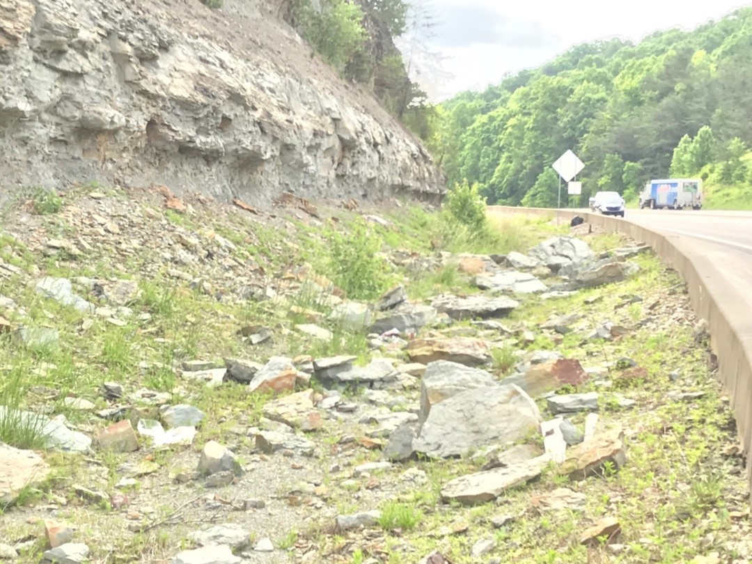
Figure 30. Catch ditch with Jersey barrier
5.4.2. Draped Mesh
Wire mesh consists of chain-link fencing, woven wire rope, or ring nets. Materials are chosen based on the anticipated size and energy of rock fall (Figure 31). Mesh is typically anchored only at the top of the slope and thus lets rocks work their way downslope in a controlled manner. Periodic maintenance is required to ensure the mesh remains in good operating condition as well as to remove fallen materials at the toe of the slope.
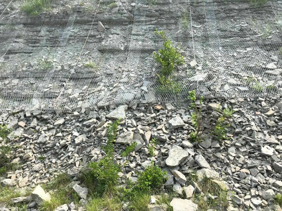
Figure 31. Rockfall mesh on I-75 near Clay’s Ferry Bridge
5.4.3. Catch Fences and Attenuators
Catch fences and attenuators are used to contain high energy rockfalls (Figure 32). Catch fences consist of chain-link mesh and woven wire rope attached to steel I-beam posts. Posts can be reinforced by up-slope anchors. Both post anchors and mesh can incorporate friction brakes to dissipate the energy of a rock fall.
Attenuators are used where rocks can fall down a narrow gully or drain (Figure 33). They typically consist of a series of draped meshes or fences which slow down and absorb the energy of a rockfall as it moves down the gully.
Periodic maintenance is required to ensure fences and attenuators remain in good working condition as well as to clean out fallen materials at the toe of the slope.
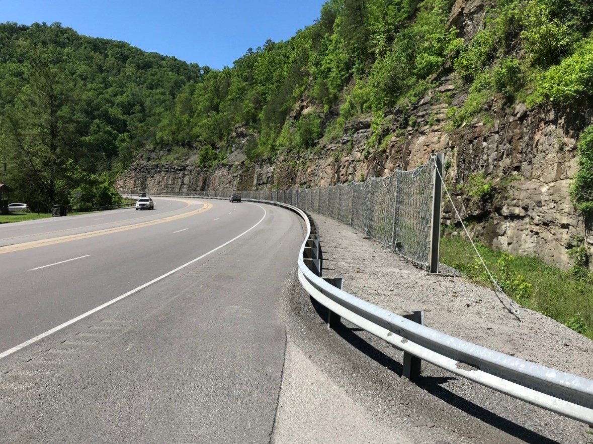
Figure 32. Rockfall catch fence on US 23
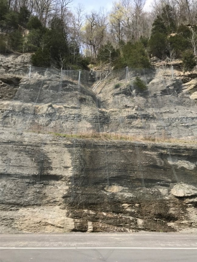
Figure 33. Mesh attenuator placed at a gully along US 23
5.4.4. Barriers
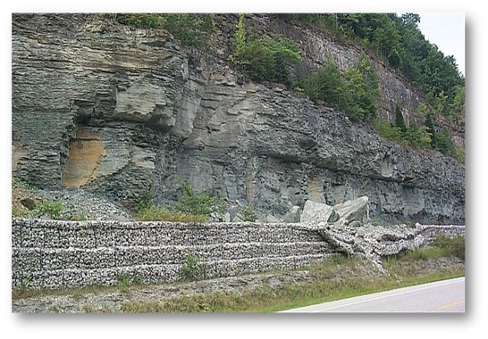
Barriers catch falling, rolling, and bouncing rocks (Figure 34). They establish a ditch-like feature where sufficient space for a normal catch ditch is not available. Barrier type and dimensions are chosen based on the amount of energy from falling rock they need to dissipate. Examples include gabions (Figure 35), large concrete blocks, geofabric walls, timber walls, soil berms, jersey barriers, and shipping containers. As with catch ditches, the zone behind the barrier requires periodic maintenance to remove fallen materials. Barriers may be damaged by fallen rock and need maintenance or replacement.
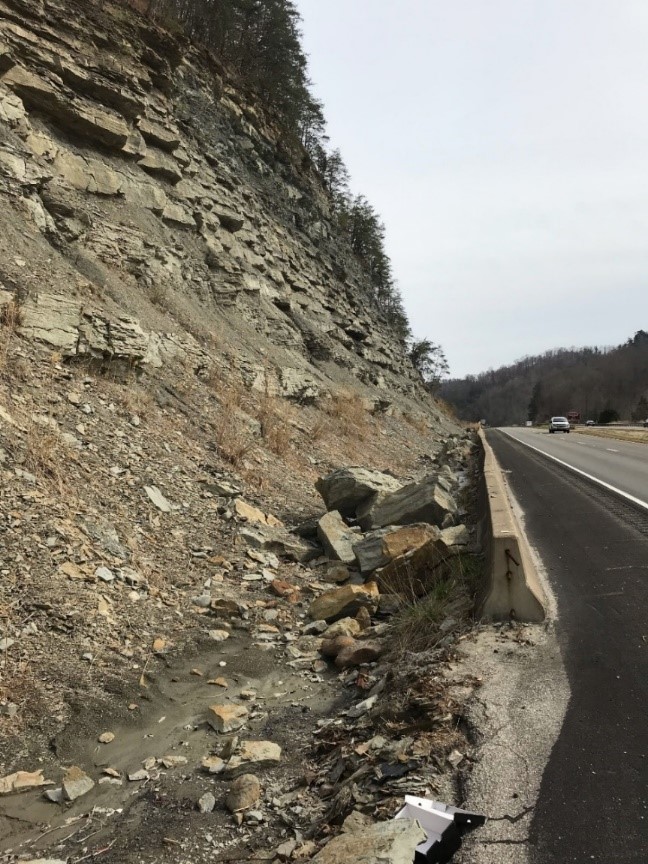
Figure 34. Jersey barrier used to contain rockfalls where there was insufficient catch ditch
Munfakh, G., Wyllie, D., and Mah, C. W., Rock Slopes Reference Manual, FHWA-HI-99-007, Washington, DC, National Highway Institute, October 1998, 393 p.
Turner, A. Keith, and Schuster, Robert L., Editors, Landslides: Investigation and Mitigation, Special Report 247, Transportation Research Board, National Research Council, National Academy Press, Washington, D.C., 1996, 673 p.

