

Search for articles or browse our knowledge portal by topic.
Traveled Way — Elements of Roadway Geometric Design
According to the AASHTO Green Book, the traveled way is the portion of a roadway intended for vehicular travel. It is sometimes referred to as driving lanes or through lanes to differentiate it from the total roadway. For geometric design purposes, it generally includes through travel lanes and may include lanes that operate as part of the vehicular travel path, such as auxiliary lanes that function like through lanes. It does not include shoulders, medians, dedicated turning lanes, bicycle/micromobility lanes, parking lanes, curbs, or sidewalks.
For roadside design applications, AASHTO’s Roadside Design Guide commonly uses the term through traveled way when establishing clear-zone and roadside-safety measurements. In this context, the clear zone begins beyond the edge of the through traveled way.
This article introduces readers to elements of geometric design for traveled ways. It does not cover pavement design as this falls outside the purview of geometric design. However, pavement characteristics impact vehicle performance and control (e.g., braking, traction), cross-slope requirements for drainage, and user comfort. As such, geometric designers need to account for pavement smoothness, surface friction, and texture (which influences skid resistance). For more information on pavement design, consult the resources listed in the Additional Resources section.
Pavement cross slope influences drainage and motorist comfort. Steeper slopes convey water off the traveled way more efficiently than flatter slopes, but they can be unsettling to navigate because motorists have to steer more to counteract lateral drift and can affect vehicle stability, particularly for vehicles with higher centers of gravity such as trucks and buses. For most paved surfaces, the recommended cross slope is 2%. Though unlikely to be encountered on a state-maintained roadway, unpaved or gravel surfaces may require steeper cross slopes. The Federal Highway Administration (FHWA) suggests maintaining cross slopes at 4 – 6% on gravel roadways to promote adequate drainage and to prevent the formation of surface depressions or potholes. Designers should consider roadway function, surface type, drainage issues, and local experience when selecting cross slopes. See Chapter 4 of AASHTO’s Green Book for additional guidance.
On tangents of typical two-lane roadways, designers achieve a 2% cross-slope rate by crowning the pavement at the centerline (Figure 1). Pavement is highest at the grade point (crown point) and slopes downward toward the edge of the traveled way. This cross slope configuration is often referred to as normal crown.
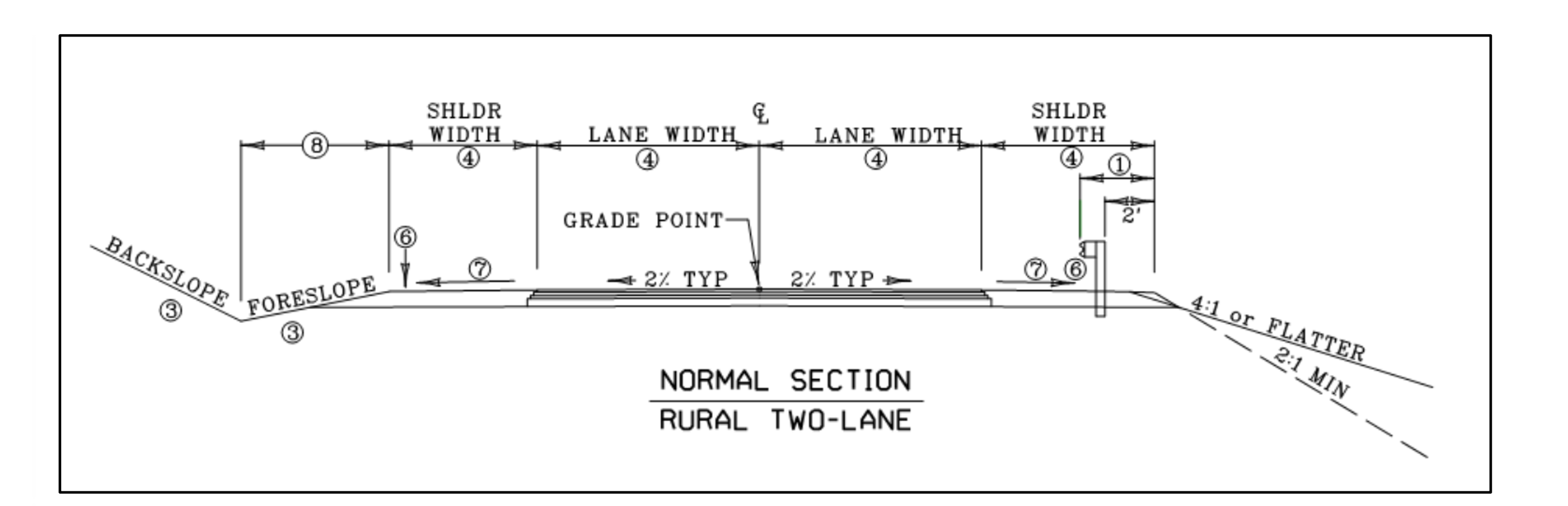
Figure 1 Typical Cross Section for a Rural Two-Lane Roadway (Source: HD Exhibit 700-5)
On divided highways, each direction is treated as a separate roadway (Figure 2). Each roadway is typically crowned about its midpoint to provide drainage toward both edges. Alternatively, a unidirectional cross slope may be applied across the entire roadway width. On unidirectional cross slopes, the high point is commonly located near the median edge, allowing the pavement to slope toward the outside edge for drainage, but the exact location may vary based on design conditions.
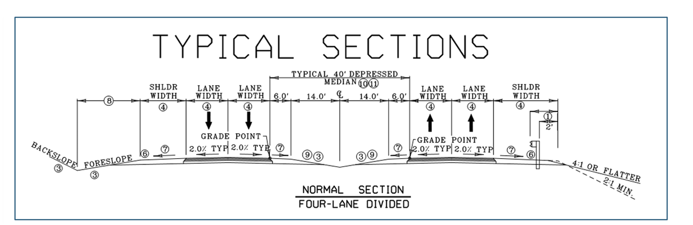
Figure 2 Typical Cross Section for a Rural Four-Lane Roadway (Source: HD Exhibit 700-7)
Roadways constructed prior to the 1970s may have slopes of 3/16 in. per foot. On some projects (e.g., widening), it is acceptable to retain this slope instead of adjusting it to achieve current standard values. When deciding if a historical slope should be maintained, designers need to evaluate if doing so is the best option to preserve roadway condition without compromising safety and operational performance. For example, designers should review crash histories to determine if a pattern of wet-weather or hydroplaning-related crashes exists. If water-related crashes have occurred, increasing the cross slope (within practical limits) may improve drainage and reduce the potential for these types of crashes. Consideration should also be given to field observations, drainage performance, and maintenance history when making this determination.
On roadways with curbs and gutters, water flow spread can be an issue (i.e., water that accumulates in a gutter and spreads laterally into the traveled way). If drainage spread is a concern, one potential solution is to increase the cross slope of the lane nearest the curb. This approach may be considered in constrained conditions and should be coordinated with drainage design to ensure proper performance. See the KYTC Drainage Manual for allowable spread for pavement inlet spacing for different roadway facility types and vehicle speeds.
Exhibits 700-01 through 700-05 of KYTC’s Highway Design Manual specify lane widths for the following roadway contexts:
- Rural local, collector and arterials
- Rural town local, collector and arterials
- Suburban local, collector and arterials
- Urban local, collector and arterials
- Urban core local, collector and arterials
Lane widths vary by context and functional classification. Typically, lane widths are measured from the center of the pavement markings (e.g., centerline to center of edge line or lane line). This provides a consistent representation of pavement width regardless of marking thickness. Roadways that accommodate high speeds and traffic volumes (e.g., interstates, freeways, parkways) generally have 12-ft. lanes.
In urban and suburban contexts, narrower lanes are more common due to right-of-way constraints, pedestrian crossings, roadside developments, and access management. In these settings, 10-ft. or 11-ft. lanes may be used to help manage operating speeds, provide space for wider shoulders, bicycle lanes, and/or pedestrian facilities, and contribute to improved safety performance in certain contexts.
One design option on multilane streets is using wider curb lanes to create space for larger vehicles to maneuver, provide a shared lane for bicycles, and establish an offset where a curb face is adjacent to the lane. On low-volume, low-speed roadways in rural and residential contexts, 9-ft. lane widths can be used.
Designers should be mindful of the relationship between lane width and safety performance. A recent study found 9-ft., 10-ft., and 11-ft. lanes may exhibit similar levels of safety performance in urban areas. In urban and suburban contexts, wider lanes have been associated with higher operating speeds, which may influence crash frequency and severity. Intuitively, a designer may think that wider lanes would improve safety because additional space can be more forgiving of motorist errors. Yet motorists often take wide lanes as an invitation to drive faster. Higher speeds can increase the likelihood of crashes as well as their severity. Many of Kentucky’s urban areas have used 10-ft. lanes for decades with good results.
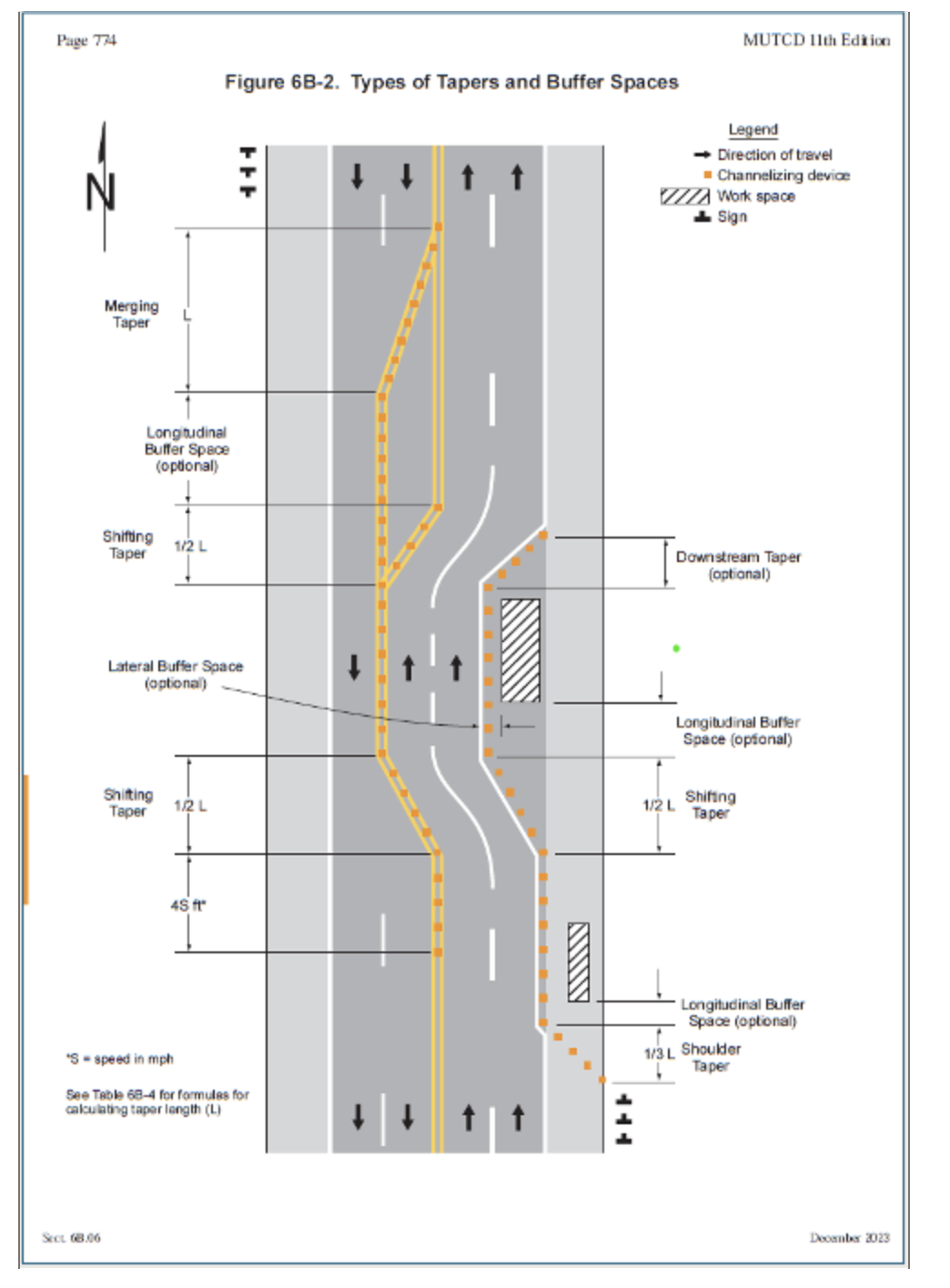
The purpose of mainline tapers is to gradually shift through traffic laterally or add/drop lanes in a smooth manner that does not disrupt vehicle flows. Tapers should be placed in areas where they are clearly visible to motorists while providing adequate sight distance. Because motorists need to be able to see the full extent of a taper, avoid designs that locate end-of-taper points along sharp curves or crests. These features limit motorist visibility and potentially degrade safety.
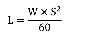
AASHTO provides several commonly used formulas to determine taper length. Table 1 lists formulas for calculating taper length, while Table 2 lists recommended taper lengths for different situations. Figure 6B-2 of the MUTCD illustrates typical merging, shifting, and shoulder taper applications used in temporary traffic control work zones.
| Table 1 Formulas to Calculate Mainline Taper Length | |
|---|---|
| Speed | Taper Length |
| ≤ 40 mph |
 |
| > 45 mph |
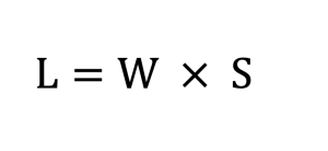 |
| Where: L = Taper Length (ft.) W = Width of Offset (ft.) S = Speed (mph) | |
| Table 2 Recommended Mainline Taper Lengths | |
|---|---|
| Type of Taper | Taper Length |
|
At Least L |
|
At least 0.5 x L |
|
At least L |
|
At least 0.5 x L |
|
|
| Note: L refers to taper length (in ft.). It is calculated using formulas listed in Table 1. | |
Safe and efficient taper lane operations require placing signs and markings upstream of and through a taper, consistent with Manual on Uniform Traffic Control Devices (MUTCD) guidance and coordinated with traffic engineering practice. These are critical for helping motorists understand where tapers start and end and how to navigate them safely without disrupting traffic flows. The first lane-drop arrows and signs should be installed well in advance of a taper. For example, if the posted speed limit is 70 mph the first sign warning motorists of a lane drop should be located about 1,250 ft. upstream of the taper, while the first arrow needs to be about 1,000 ft. upstream.
Designers should be mindful of how motorists could potentially interpret signs and markings and how those interpretations influence behaviors and reverberate through traffic operations. Often motorists begin merging immediately after they detect a sign, or they will opt to not use a lane if they know it ends shortly. The HKP article Applying Knowledge of Human Factors in Roadway Design provides strategies for systematically considering human factors in the design process. Additionally, designers should consult the MUTCD (e.g., Chapter 3B) and KYTC’s Traffic Standard Drawings for more information on signing and marking schemes for tapers. Designers should also speak with a District, Central Office, or project traffic engineer to verify their approach to signing and markings promotes safe taper lane operation.
When reducing the number of through lanes, designers should generally maintain continuity of the inside through lane and drop the outside lane. This configuration aligns with motorist expectations, because most drivers associate the presence of slower-moving vehicles, entering traffic, and exiting traffic with the outside lane. Maintaining the inside lane as the continuous through lane also minimizes disruption to higher-speed traffic and reduces the need for motorists using the inside lane to make lane changes.
Despite this general rule of thumb, site-specific conditions should ultimately dictate which lane is dropped. In some cases, it is in fact more appropriate for the outside lane to continue and the inside lane to end, particularly where roadway alignment, downstream lane assignments, major turning movements, route continuity, or phased construction considerations make this arrangement more intuitive to motorists. The selected configuration should always prioritize clarity, consistency, and conform with driver expectations.
When adding a lane, the new lane should typically be introduced on the outside of the traveled way. This practice is consistent with common applications such as acceleration lanes, auxiliary lanes, and climbing lanes. It is also generally easier for drivers to recognize and navigate. Adding a lane on the inside should be limited to situations where operational or geometric conditions clearly support that choice.
Lane drops and additions should be located where the full transition is clearly visible and where motorists are not required to make multiple decisions at once. At lane drops, decision sight distance should be provided in advance of the transition. Avoid placing these transitions near intersections, major access points, sharp horizontal curves, or crest vertical curves where sight distance may be limited or driver workload is already elevated.
American Association of State Highway and Transportation Officials. (2018). A Policy on the Geometric Design of Highways and Streets, 7th Edition. American Association of State Highway and Transportation Officials, Washington, D.C. https://store.transportation.org/item/collectiondetail/180.
- Section 4.2 offers an in-depth discussion of the traveled way. It reviews issues such as rate of cross slope, skid resistance, and hydroplaning.
AASHTO Roadside Design Guide.
Consult the following resources for more information on pavement design and its influence on geometric design of the traveled way:
- KYTC’s Highway Design Guidance Manual (Section HD-1000)
- KYTC Pavement Design Webpage
- Pavement Design Guide
- KYTC Pavement Design Web Application
Federal Highway Administration. (2023). Manual on Uniform Traffic Control Devices for Streets and Highways. US Department of Transportation, Washington, D.C. https://mutcd.fhwa.dot.gov/kno_11th_Editionr1.htm
- Chapters 3B and 6B include signing and marking plans for taper lanes.
- Applying Knowledge of Human Factors in Roadway Design
- Design Speed
- Stopping Sight Distance
- Horizontal Curves
- Vertical Curves
- Shoulders