Search for articles or browse our knowledge portal by topic.
Geotechnical Aspects of Construction
The purpose of a geotechnical investigation is to ensure the stability, safety, and life-cycle performance of cuts, embankments, structure foundations, retaining walls, pavements, and other aspects of transportation projects. The outcome of an investigation are design, construction and maintenance recommendations that, when followed, help insure the performance and longevity of these assets. Failure to follow these recommendations increases the risk of unsatisfactory performance of the assets resulting in increased construction, maintenance, repair, and replacement costs as well as increased indirect costs such as user costs, claims, delays, or Department budget impacts.
Many construction practices related to geotechnical aspects are outlined in the Standard Specifications, Special Notes, or Special Provisions. Other practices may be outlined in the Geotechnical or Structure Note Sheets that are included in the plans. KYTC Geotechnical staff are available to help construction personnel understand the importance of these practices as well as how to inspect and document the work.
A soil mass consists of three phases – solid particles, air, and water. Air and water fill the void spaces between the soil particles. To reduce the void spaces and increase the density, loose soil must be compacted. Compaction should be done under controlled moisture conditions using a given amount and type of compaction energy. Compaction results in the following benefits:
- Increases the strength and stiffness of the soil.
- Decreases the amount of settlement under load.
- Reduces the permeability of the soil.
- Reduces the potential for volume change (i.e., shrinkage, swell, or frost heave) of the soil.
Compaction directly influences slope stability, settlement, structure movement, retaining wall stability, and pavement performance. As such, compaction is one of the most important earthwork construction activities to be performed. For example, improper compaction of embankment materials at bridge end bents or abutments can contribute to excessive settlement and the “bump at the end of the bridge” as well as rotation or movement of substructures, excessive deflection at bearings, excessive closure or opening of joints, disruption of bridge end drainage, and overstressed pile foundations. Geotechnical plan sheets for line and grade projects provide information on the maximum density and optimum moisture content for soils encountered on a project.
Sections 206 and 207 of the Standard Specifications provide requirements for compaction of embankments and subgrades, respectively, while Section 603.03.04 provides information for compaction of backfill around structures. Special Provision No. 69 along with Standard Drawings RGX-100 and RGX-105 provide information on compaction of embankments at bridge end bents.
Compaction requirements vary depending on the soil or rock material being compacted as outlined in the Standard Specifications. Items to be aware of during compaction are as follows:
- Lift Thickness – Lift thicknesses for different types of embankment materials are outlined in the Standard Specifications. Thicker lifts are more difficult to compact as the energy applied from the compaction equipment may not be able to penetrate through the lift.
- Moisture Content – Soils have an optimum moisture content for a given compaction energy at which it can achieve maximum dry density. Moisture content of soils generally should be between -2% and +2% of the optimum moisture content during compaction.
- Equipment – Compaction equipment should be selected to produce the required results for the materials being compacted (Figure 1). Granular materials such as aggregates, gravels, and sands usually need vibratory compaction where cohesive soils such as clays and silts need impact or kneading force (e.g., sheepsfoot rollers). When backfilling adjacent to structures, lighter weight equipment such as plate, jumping jack, or small smooth drum compactors should be used along with thinner lifts to avoid exerting excessive stresses on the structure.
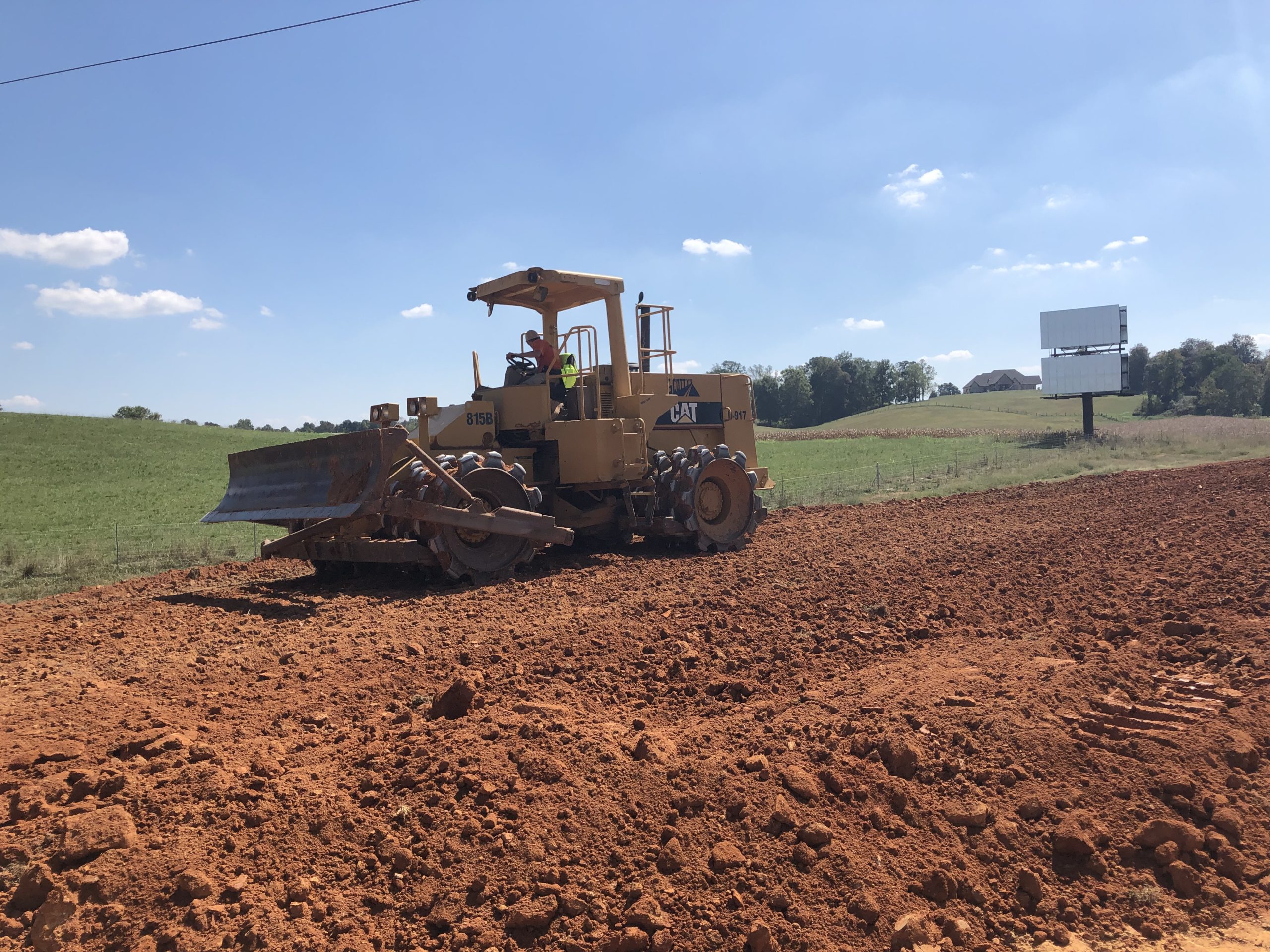
Figure 1. Sheepsfoot roller compacting fill material
- Non-durable Shale – Non-durable shale will break down over time when exposed to water. Unless special compaction methods are used, embankments built of non-durable shales will settle, may experience slope failures, and may have undesirable structure movement/distress. The special compaction requirements serve to break down the shale during construction and thus reduce the void space present in the material post-compaction. Section 206.03.02.D of the Standard Specifications outlines the requirements for compaction of non-durable shales.
- Structure Backfill – Backfill materials around structures, including granular materials, also require compaction. End dumping materials into a backfill area results in a loosely packed fill that will settle over time and can lead to a “bump at the end of the bridge”, settlement over pipes and culverts, excessive stresses and movement of bridge substructures, or movement of retaining walls. Backfill materials around structures should be placed in thin lifts and compacted using light-weight compaction equipment in accordance with Section 603.03.04 of the Standard Specifications to densify the material and increase the particle-to-particle contact.
Piles are used to support many of the bridge substructures across Kentucky. Piles generally fall into two categories of support:
- Point Bearing – Capacity is achieved by the pile tip bearing on a hard layer, which is typically bedrock. Point bearing piles make up most of the pile installations in Kentucky.
- Friction Piles – Friction piles achieve capacity from the friction between the pile and surrounding soil. Friction piles are typically used in areas where bedrock is too deep (e.g., far Western Kentucky or areas around major rivers) for point bearing piles to be cost effective. Friction piles may tip on and achieve significant capacity from a harder soil layer.
3.1 Pile Types
- Steel H-Piles – Steel H-Piles are used for most pile foundations in Kentucky. They are used in both point bearing and friction pile situations. When used in point bearing applications on bedrock, pile points are usually installed on the end of the pile to help the pile penetrate and grip the bedrock surface. Pile points should not be installed on H-piles when used in friction pile conditions as they tend to create an oversize hole when driving the pile. This oversized hole reduces the contact between the pile and the soil resulting in less pile capacity and piles being driven deeper than the plans indicate (i.e., pile quantities are overrun). The plans will specify when pile points should be installed on the pile tip.
- Steel Pipe Piles – Steel pipe piles may be used for friction piles. Pipe piles are typically used in situations where large pile capacities are needed, where lateral loads such as barge impact or earthquake may be possible, or when H-piles cannot achieve the required capacities without excessive pile quantities (i.e., excessive lengths or numbers of piles). Pipe piles may be driven open-ended or with a pile cap to create a closed end (Figure 2). Pipe piles can be left hollow after installation or may be backfilled with sand, gravel, or concrete as specified in the contract documents.
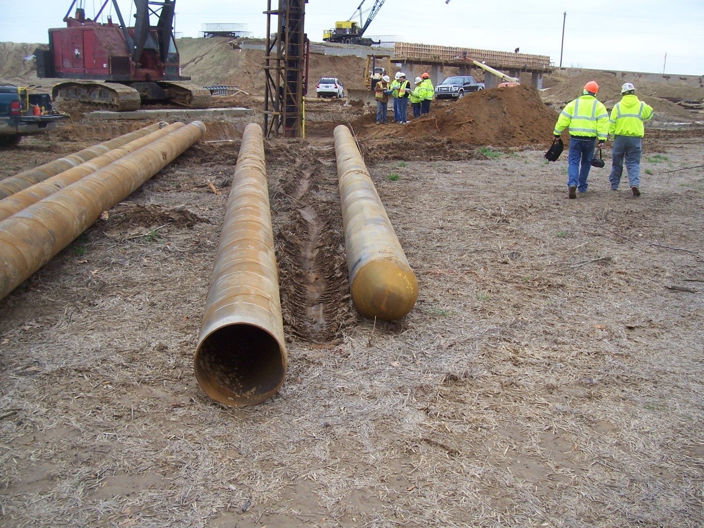
Figure 2. Pipe piles with conical point attached to one of the piles
- Other Pile Types – Other pile types include the following:
- Precast or Prestressed Concrete Piles – Concrete piles have been used by KYTC in the past but are no longer common because they are difficult to splice and/or cut off. Concrete piles are also more likely to be damaged during driving and require careful control of the driving systems (e.g., hammer, helmet, and cushions) and installation processes.
- Shell Piles – Shell piles are like pipe piles, but the shell is often fluted, corrugated, and/or tapered. They often require a mandrel placed inside the pile during driving to prevent damage or collapse of the shell. The shells are usually filled with concrete after driving. Shell piles are no longer commonly used.
- Timber Piles – Timber piles can be found on some older, smaller bridges across the state. Timber piles were often used as friction piles on small state, county, or local bridges in far western Kentucky, but they can be found in other locales across the state. Timber piles placed entirely below the water line can be remarkedly well preserved, but timber piles that extend above the water line are subject to rot and damage.
- Micropiles – A micropile consists of a drilled-in small diameter casing, often socketed into bedrock, which then has a threaded steel bar inserted and filled with grout. Micropiles can sometimes be installed through an existing footing or pile cap. Micropiles are particularly useful for retrofitting structures to provide additional capacity (Figure 3).
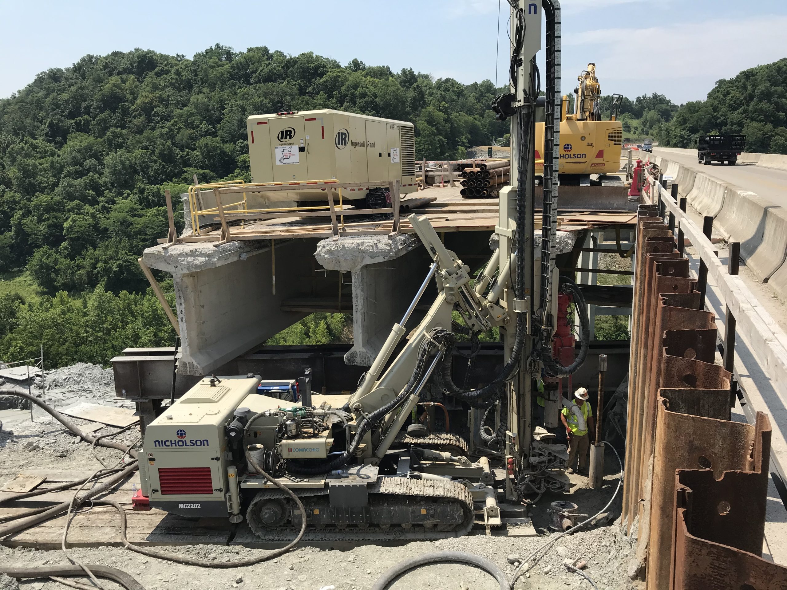
Figure 3. Micropile installation to retrofit an existing bridge end bent
3.2 Pile Installation
Section 604 of the Standard Specifications provides information about the materials, equipment, and installation of piles.
3.2.1 Pile Layout and Orientation
It is important that piles are installed as indicated in the plans. Piles installed incorrectly may not provide the needed support for the substructures and thus may result in distress to the structure.
3.2.1.1 Location
The contractor should carefully lay out the location of each pile. It is beneficial for the contractor to construct a template, often out of scrap wood on the construction site, which will allow accurate placement of each pile. Piles that are installed in incorrect locations or move out of location significantly during driving should be removed and reinstalled.
3.2.1.2 Spacing
Piles should be installed at the correct spacing (see above about template). This is particularly important for friction piles, like closed end pipe piles, as they displace material as they are driven. This displaced material densifies the soil adjacent to the pile. This densified soil may make it more difficult to drive the next pile if the piles are spaced too closely together.
3.2.1.3 Orientation
Piles should be installed with the proper orientation as indicated on the plans. This is particularly important for H-Piles used in integral end bents. Integral end bents are allowed to move with the thermal expansion of a bridge. Since H-Piles have different bending strengths in different directions, this can impact the ability of the integral end bent to move. When an integral end bent cannot move, it can impart additional loads to the bridge superstructure.
3.2.1.4 Batter
Piles, and particularly point bearing piles, may be battered at an angle. This batter helps the pile resist lateral loads from the structure. Piles not appropriately battered may not provide the lateral load capacity needed to help the substructure resist movement. Batter should be measured and monitored during pile installation to help insure proper placement.
3.2.1.5 Installed Depth
Piles should be marked prior to installation with depth measurements (feet and/or inches) so that blows per foot or inch can be accurately determined, and the installed length of pile can be documented (Figure 4). Marking the pile in inches is particularly useful when the pile is near the expected penetration depth or near the end of driving as it aids in getting a more accurate count of blows per depth unit.
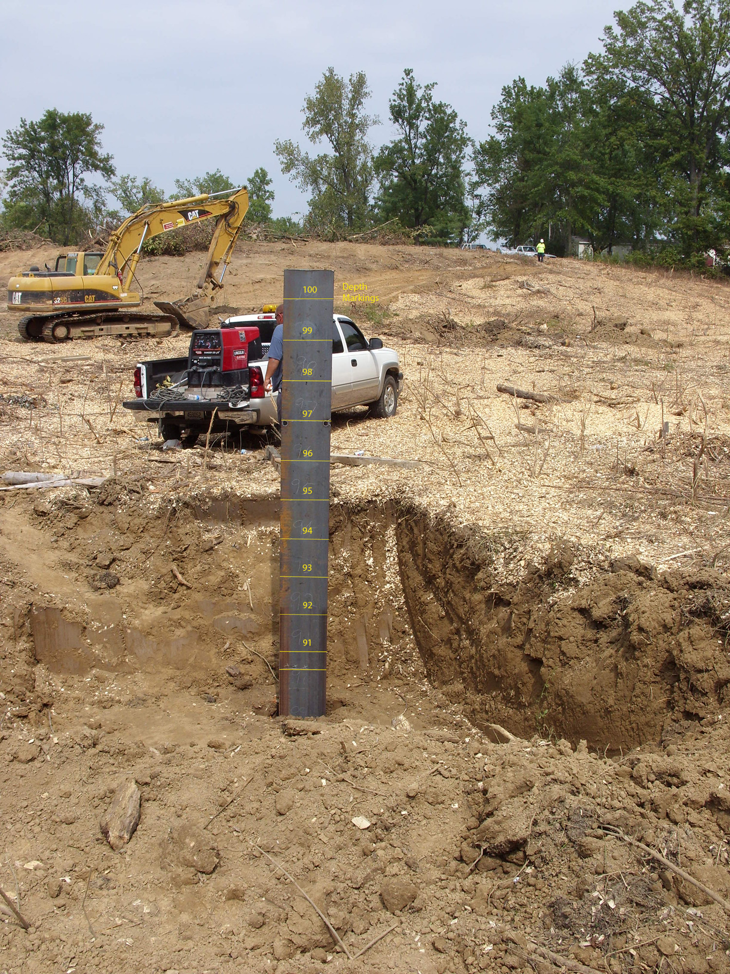
Figure 4. H-Pile with length measurements marked on pile
Pile capacity analyses are conducted during design to estimate the bearing capacity of a pile for given subsurface conditions. Pile tip elevations are then selected from this analysis to achieve one or more of the following design requirements:
-
- Axial Capacity – the tip elevation is set to provide capacity to support axial compressive loads from the structure.
- Uplift Capacity – The tip elevation is selected to provide sufficient capacity to resist tensile (uplift) loads from the structure. Uplift loads on piles can occur due to conditions such as wind loads, impact loads (such as barge strikes), and earthquake loads.
- Lateral Capacity – Lateral loads (loads perpendicular to the pile axis) can occur due to conductions such as wind loads, impact loads, earthquakes, vehicle braking, and temperature loads. Often piles require a minimum embedment to achieve sufficient capacity to resist lateral loads.
- Scour – Scour is the removal of soil or rock due to the flowing water. When scour occurs, it removes soil around the pile that would otherwise contribute to the axial, uplift, or lateral capacity of the pile. In these situations, the pile tip elevations would be set to embed the pile a sufficient distance below the estimated scour depth so that the required capacities could be achieved.
While minor differences in installed tip elevations versus the design tip elevations are expected during construction, construction personnel should coordinate with the structure designer and geotechnical personnel if difficulty is encountered in driving piles to the estimated tip elevation or if piles are driving well past the estimated tip elevation. Changes in pile driving procedures or foundation design may be needed to remedy the situation. Typical causes of problems in driving piles to the required depths are as follows:
-
- The pile driving hammer does not have the required energy to appropriately drive the pile or does not meet the Hammer Criteria provided in the plans. This could mean that the hammer operates inefficiently and is not applying enough energy, the hammer is too small and cannot apply sufficient energy, or the hammer is too large and applies too much energy.
- The pile being installed is not as specified. This could be a pile that is larger or smaller than required by the plans. It could also be that pile tips have been either added or omitted from the piles when the plan requirements were for the opposite condition.
- Piles are damaged during installation. Piles that are driven using oversized hammers can collapse, bend, or break. Pile Splices that are poorly constructed or welded can break due to driving stresses. In both cases the entire pile may appear to be driven without achieving capacity, but only a portion of the broken pile penetrates the subsurface.
- Piles are installed in an inappropriate sequence resulting in densification and confinement of the foundation soils. See Driving Sequence below concerning driving sequence for piles.
- The subsurface conditions are different than the conditions assumed during design. Changes in groundwater levels are common due to precipitation changes during the various seasons, and these groundwater levels directly impact pile capacity and driving resistance. In some instances, the anticipated soil conditions during design are different than that encountered during construction.
3.2.1.6 Driving Sequence
Driving sequence is important for pile groups. Pile groups should be driven from the inside piles to the outside piles, or from one end to the other end for a single row of piles, to minimize the impacts of densification due to pile driving. If the outer piles in a group are driven first, it serves to confine the soil within the middle of the group leading to increased soil densification as the pile installation moves toward the center of the group. This can prevent the piles in the center of the grouping from being driven to the required tip elevation. Not installing piles to the correct depth can result in the pile not having the needed axial, uplift, or lateral load carrying capacity which affects the ability of the structure to resist not only live and dead loads but also loads from barge impacts, scour, and earthquakes.
3.2.2 Pile Splices
Pile splices for steel piles, when needed, should follow the details of Standard Drawings BPS003, BPS009, BPS011, or BPS012 (Type drawing # into table. Do not include dashes or spaces) depending on the pile type. These standard drawings address the spice plates and welding that is required. As an alternative, there are manufactured splice connectors that can be used. Welding of splice plates or the manufactured connectors must be performed by certified welders. Correct welding of the splices is important to ensure integrity of the pile. Improper or poor welds may break during driving, allowing the pile sections to shift relative to each segment. Broken piles usually result in problems installing the pile or with excessive lengths of pile being installed. Improper, poor, and broken welds also impact the load capacity of the piles, particularly with uplift loads. Wind, barge, scour, or earthquake loads may result in uplift loads on the pile, and poor or broken welds result in only part of a pile available to provide uplift resistance.
3.2.3 Pile Driving Criteria
3.2.3.1 Point Bearing Piles
Driving criteria for point bearing piles is determined by the practical refusal criteria in Section 604.03.07.C of the Standard Specifications. Capacity formulas are not required in this instance since the formulas were not developed for point bearing piles. The bearing capacity of the pile is based solely on the structural capacity of the pile.
3.2.3.2 Friction Piles
Blow counts must be recorded during friction pile installation to determine capacity and when to terminate driving for friction piles. Piles should be marked prior to installation with depth measurements (feet or inches) so that blows per foot or inch can be accurately determined. A reference method to help the inspector accurately determine the penetration depth of the pile should be used.
Capacity of the pile during initial driving is evaluated by using the Modified Gates Dynamic Formula as outlined in Section 604.03.07.B of the Standard Specifications. A spreadsheet for the Modified Gates equation is available on the Division of Structural Design, Geotechnical Resources web page to assist in recording blow counts and calculation of the pile capacity. This formula should only be used for piles with a nominal capacity of 300 tons (600 kips) or less. It is also important to make sure this information gets transferred to the as-built plans and is provided to the Division of Structural Design. Note that the Modified Gates Dynamic Formula is not to be used to evaluate the capacity of a pile during restrike after setup since it was calibrated to provide ultimate (after pile setup) pile capacity based on initial driving data.
Dynamic monitoring of pile driving is sometimes specified to evaluate pile capacity and driving criteria. Common reasons for specifying dynamic monitoring are piles with large nominal capacity, pile sizes or types that are not normally used, piles with unusual loading conditions, or piles where driving of the pile may be difficult. See Pile Testing for more information about dynamic monitoring of pile driving.
3.2.4 Hammer Criteria
Plan notes give recommendations for a range of hammer energies recommended for driving the piles. These energies are based on a wave equation analysis which evaluates the ability of a hammer to efficiently drive a pile to the required depth given a specific pile type and subsurface condition. The energy ranges recommended for the hammers are chosen so that the pile can be driven without excessive blow counts or stresses that may damage the pile. These energy ranges are also critical to ensure proper seating and adequate practical refusal for point bearing piles. If a hammer that meets the criteria has difficulty installing the pile, it could indicate that the hammer is not operating correctly or that the subsurface conditions are different than assumed in the analysis. Recommendations are given for open-ended diesel (OED) hammers, which is the most common hammer utilized on KYTC projects, so construction personnel should contact the Geotechnical Branches for additional recommendations if a different type of hammer is used on a project.
3.2.5 Pre-Drilling
Pre-drilling for pile installation may be required. Pre-drilling is often used where bedrock may be relatively close to the bottom of the pile cap and drilling into bedrock is used to help ensure a minimum 10’ length of pile below the cap. This is a common practice for situations where an integral end bent is used. In other instances, pre-drilling may be specified to penetrate soils with large boulders which would damage or prevent penetration of the piles during driving.
When pre-drilling is specified into bedrock, it is important to seat the pile into the rock socket. It is often difficult to remove all the cuttings from the pre-drilled hole, and if the pile is not properly seated it may result in settlement of the structure. The seating is usually conducted with a few blows of a pile hammer. It is also important to properly backfill the hole before seating the pile so that the pile does not move around during the seating process. For very short piles (around 10’ in length) that are pre-drilled into bedrock, it is important to follow the hammer energy recommendations provided in the plans since using larger hammers to seat the pile can result in overstressing and damaging the pile.
3.2.6 Pile Testing
Testing of a pile is sometimes recommended for piles where large or critical load conditions are being placed on the foundation. The most common test recommended is dynamic monitoring. Dynamic monitoring involves placing instrumentation on the pile to measure strain and acceleration during real-time driving of the pile. This test provides information on the bearing capacity of the pile, distribution of soil resistance on the pile shaft, end bearing resistance on the pile tip, pile integrity or damage, hammer performance, and driving criteria for the remainder of the piles in the foundation unit. Dynamic tests may also be conducted at some time (typically 3 to 7 days depending on foundation soil conditions) after initial driving of the pile to measure “setup” of the pile.
Other tests that may be performed on piles are static or dynamic load tests to measure capacity of pile and integrity tests to check for pile damage. Conducting full-scale load tests can require substantial equipment, time, and money to complete. As such, full-scale load tests are typically only conducted for piles (or drilled shafts) that are heavily loaded, have sizes that are not commonly used, or for structures that have critical loading conditions.
3.3 Pile Driving Records and Forms
Pile driving records, forms, and as-built plans shall be submitted to the Division of Structural Design for record keeping. This includes forms and reports documenting lengths of pile installed, blow count records, dynamic testing reports, and load test reports. This information is critical to documenting the as-built status of the bridge. The as-built information is useful in determining whether a bridge is susceptible to scour or whether the existing foundation can be reused when a bridge is replaced, widened, or improved. Geotechnical staff can also refer to the as-built plans to verify and improve their design methods or to supplement investigations needed for future bridge replacement, widening, or improvement projects.
Drilled shafts are a type of cast-in-place pile. They are constructed by drilling a hole into soil or bedrock, placing a reinforcing cage into the hole, and then placing concrete to fill the hole. A single drilled shaft can resist very large loads, effectively replacing a group of driven piles. Drilled shafts may require less area than a typical footing and thus can be built in smaller footprints. This allows drilled shafts to be feasible in situations near railroads, existing structures, or constricted places where footing excavations, noise, or pile driving vibrations are not desirable. Special Note 11C covers construction of drilled Shafts.
Casing may be used to prevent collapse of the shaft boring prior to placement of the concrete. For KYTC projects where the drilled shaft extends into bedrock (i.e., a rock socket), permanent casing is often specified to prevent soil from collapsing into the hole. In other cases, a drilling slurry may be specified to help maintain stability of the shaft boring, to resist groundwater infiltration or pressures, or to prevent deterioration of the subsurface materials (e.g., deterioration of non-durable shales).
A benefit of drilled shafts is that the drilling process allows the inspection and verification of the soils and rock encountered. This is particularly important for drilled shafts used in karst conditions where there may be voids or cavities within the limestone bedrock. In cases where karst may be encountered, the shaft and casing may be extended to seal off the cavities and bear on more suitable materials. Plans may call for additional subsurface borings at each shaft location prior to shaft construction to verify and/or adjust shaft lengths.
Reinforcing cages must be properly tied and stabilized to maintain their integrity. Lifting the cages and placement into the drilled hole must be carefully conducted to prevent damage and distortion of the cage. The cages must also be carefully tied off and anchored once placed in the hole so that they maintain their position during the concrete placement process.
Concrete placement may be conducted in either dry or wet holes. For dry holes, concrete placement proceeds from the bottom to the top of the hole. Wet holes typically occur in locations where the groundwater is high or in conditions where shafts are installed through standing water (e.g., rivers and lakes). In wet situations a tremie method is used to place the concrete. The tremie is sealed to keep water out and is placed to the bottom of the shaft. The tremie is then loaded with concrete and then slowly raised while continuing to be filled with concrete. The bottom of the tremie must remain embedded within the concrete during the placement process to prevent contamination or dilution of the concrete. As the concrete is placed, the concrete level rises and pushes any water, mud, slurry, and contaminated concrete out of the shaft. Slump and workability (time the concrete is fluid before setting) of the concrete is an important factor for drilled shafts as concrete must be able to flow around the reinforcing cage, remain fluid as the concrete is placed from bottom to top of the shaft, and not setup prematurely as large shafts (both in diameter and length) may take a long time to place the concrete.
Often instrumentation is specified for drilled shafts to ensure that there are no defects that may impact their strength or performance. These defects can include soil inclusions from sidewall collapse, poor cleaning of cuttings from the hole, contaminated concrete from placement in wet conditions, or poor-quality concrete. The instrumentation may include crosshole sonic logging (CSL), thermal integrity profiling (TIP), or pile integrity testing (PIT). For shafts supporting critical structures or large loads, load testing may be performed.
KYTC Geotechnical Staff are available to assist construction personnel who are unfamiliar with drilled shaft construction to identify and understand needed inspection items, construction methods, testing processes, and as-built documentation.
Footings are often used to support bridges, retaining walls, and culvert wingwalls. Footings for bridge substructures in Kentucky typically bear directly on bedrock. Retaining wall and culvert footings often bear on soil but may bear on bedrock. In either case it is important to excavate and construct footings correctly to provide the support needed for the structure. Section 603 of the Standard Specifications covers foundation preparation and backfill.
Footing excavations should be clean of debris, loose soil, loose rock, and standing water prior to placing concrete. Loose material or water in the excavation can prevent good contact between the concrete and the foundation soil or bedrock. When the footing does not have good contact with the foundation material, the footing and thus the structure may be susceptible to horizontal sliding, rotation, or settlement along the base of the footing.
Footing excavation and construction should take place as quickly as possible. Excavations left open for long periods can result in deterioration of the foundation materials due to exposure to rainfall, standing water, or excessive drying. This is especially true for foundation materials consisting of soil or non-durable shales. If a footing excavation is left open for an extended period, the bottom of the excavation should be cleaned once again before placing concrete.
Where scour may be possible, the plans will call for a minimum embedment of the footing into bedrock. This embedment is usually 1 or 2 feet depending on whether the bedrock is durable or non-durable. In these situations, the footing should not be formed but instead the concrete should be placed so that it is in direct contact with the sidewalls of the excavation. This direct contact helps prevent scour holes from forming and undermining the footing.
Over-excavation of foundation soils and replacement with granular material (e.g., No. 1s, 2s, 23s, Select Granular Embankment, etc.) may be recommended in situations where the foundation soils are soft and cannot provide sufficient support for a footing or retaining wall. If the depth to bedrock is relatively shallow, the recommendation may call for excavation and replacement of the soils to bedrock. The granular material serves to spread the load from the foundation over a larger area, provide stronger material to support the footing, and may reduce settlement of the final structure. A geotextile may be recommended to separate the granular material from surrounding soils. The granular material should be compacted to densify the material and reduce the potential for settlement.
Satisfactory performance of retaining walls depends on proper construction of the foundation and backfill. Failure to properly prepare the foundation and backfill can result in tilting, overturning, horizontal displacement, structural distress, and global stability failure of retaining walls. The items listed above for Compaction and Footing Excavations are essential components of wall construction. Section 613 of the Standard Specifications covers construction of retaining walls.
Control of surface and subsurface drainage is essential to satisfactory performance of a retaining wall. Water can saturate the wall backfill, and this reduces the strength of the backfill material as well as places additional loads on the retaining wall. Subsurface drainage items such as granular backfill, perforated pipes, and/or geocomposite drains are placed behind the wall to intercept water in the backfill. Weep holes in the wall facing also allow water to drain out of the backfill. Surface drainage should be directed away from the wall or otherwise controlled to minimize infiltration into the backfill.
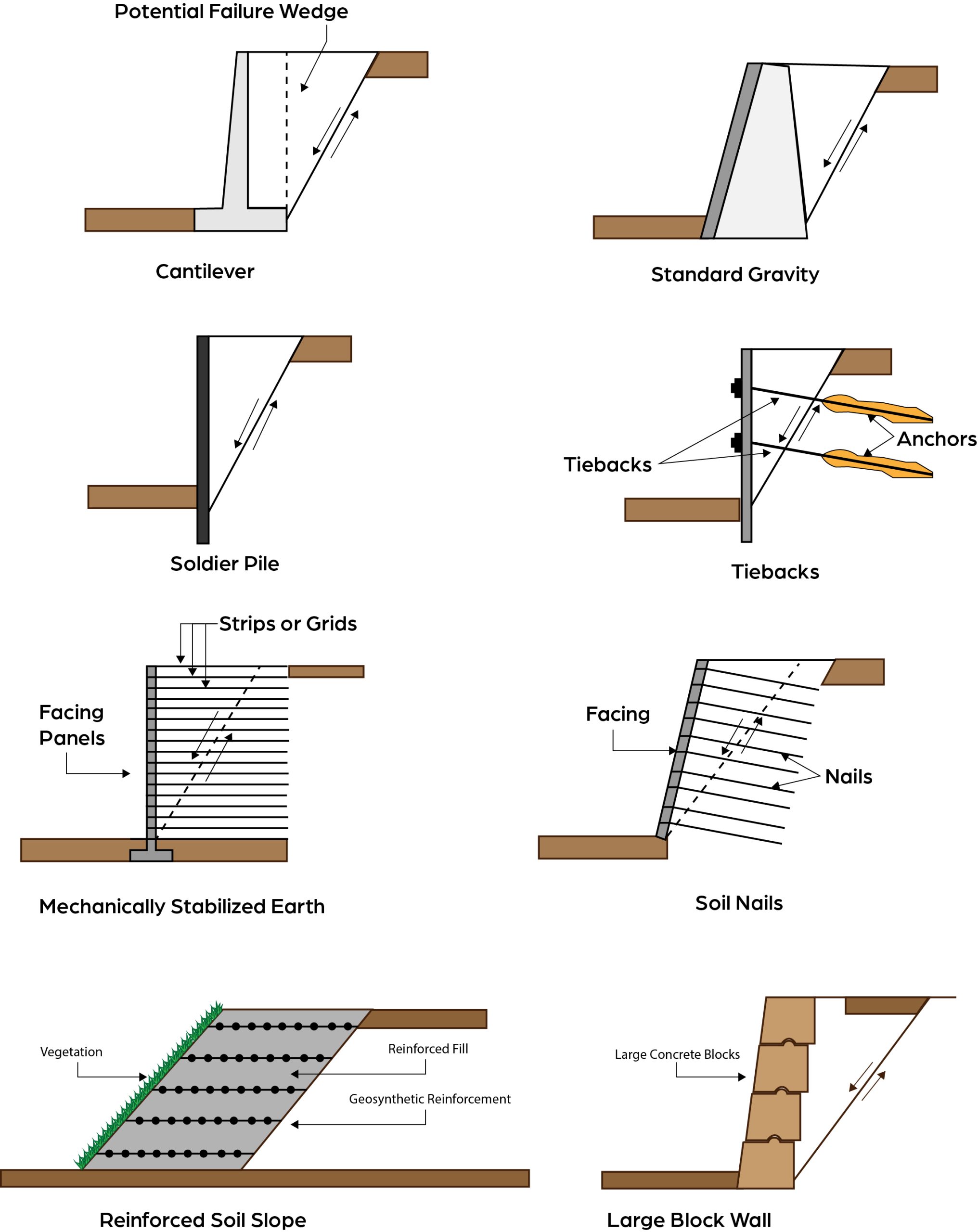
Commonly utilized wall types are:
- Cast-in-place (CIP) Concrete – CIP concrete retaining walls consist of reinforced concrete and depend on the shape and size of the wall to resist loads. CIP walls are specifically designed for a particular location.
- Standard Gravity – A standard gravity wall is an unreinforced concrete wall that depends on its shape and weight to resist loads. Standard gravity wall dimensions and construction details can be found in Standard Drawings BGX023 and BGX024 (Type in drawing # into table. Do not include dashes or spaces). Standard gravity walls can be used in situations where the total wall height is less than 12 feet and where the loading conditions meet the requirements shown in the Standard Drawings. Wall loading conditions and dimensions that fall outside those shown in the Standard Drawings require a special design.
- Mechanically Stabilized Earth (MSE) – MSE walls have closely spaced reinforcement elements placed in the backfill that extend beyond the anticipated failure plane. The reinforcement strips are commonly steel strips, bars, or woven wire elements. The backfill material is Structural Granular Backfill with additional requirements to prevent corrosion of the reinforcement. Facing elements, which are commonly reinforced concrete panels, are used to prevent raveling and deterioration of the wall backfill but do not provide primary structure support. MSE walls are proprietary, pre-approved systems that are designed by the manufacturer/supplier for a specific location. These designs are required to be submitted for review prior to construction (see Special Note for MSE Retaining Walls). During construction of MSE walls it is important to ensure proper alignment and batter of the wall facing panels, proper placement of the reinforcement, and compaction of the granular backfill.
Other wall types may be used in specific situations. Often these wall types require a specialty contractor for installation. When these wall types are specified, it is beneficial to contact KYTC Geotechnical personnel for assistance about the construction details and inspection required. These wall types include:
- Soldier pile – Soldier pile walls consist of vertical structural elements, which are typically a steel beam or pile section, installed on a given spacing (Figure 5). The vertical elements are typically installed in a drilled hole, and they are commonly embedded into bedrock sockets to help provide stability for the wall. Wood or concrete lagging elements are then placed between the soldier piles to prevent raveling of the backfill material. Solder piles walls are often placed in cut sections, and lagging is installed as the cut progresses downward. A cast-in-place concrete facing can be placed after the wall excavation is completed. Drilled shafts, either on a given spacing or adjacent to each other, can be used as soldier piles in instances where the horizontal loads on the wall are very large.
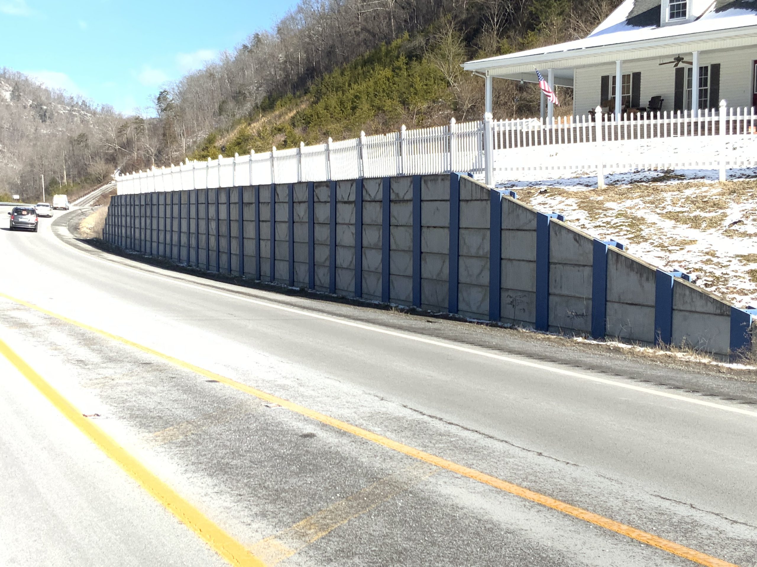
Figure 5. Soldier pile wall consisting of steel W sections with precast concrete lagging panels
- Tieback – Tieback walls are like soldier pile walls except that anchors are installed through the wall face to provide additional resistance to loads. These anchors are typically steel strands that are inserted and grouted into a drilled hole. The strands are then stressed to provide additional resistance. Tieback walls are typically used in cut slope situations where large horizontal loads are expected. They are well suited to help correct landslide situations.
- Soil Nail – Soil nail walls consist of threaded steel rods inserted and grouted into bored holes. The grouted nails serve to reinforce the backfill. Soil nail walls typically are placed in cut sections, and the nails are installed as the cut progresses downward. The nails are inserted on a given spacing, and a facing is then connected to the nails to keep the backfill from raveling. The facing can be temporary or permanent and is commonly composed of shotcrete. In areas where the facing may be visible to the public, the shotcrete can be sculpted to provide an aesthetically pleasing look (Figure 6).
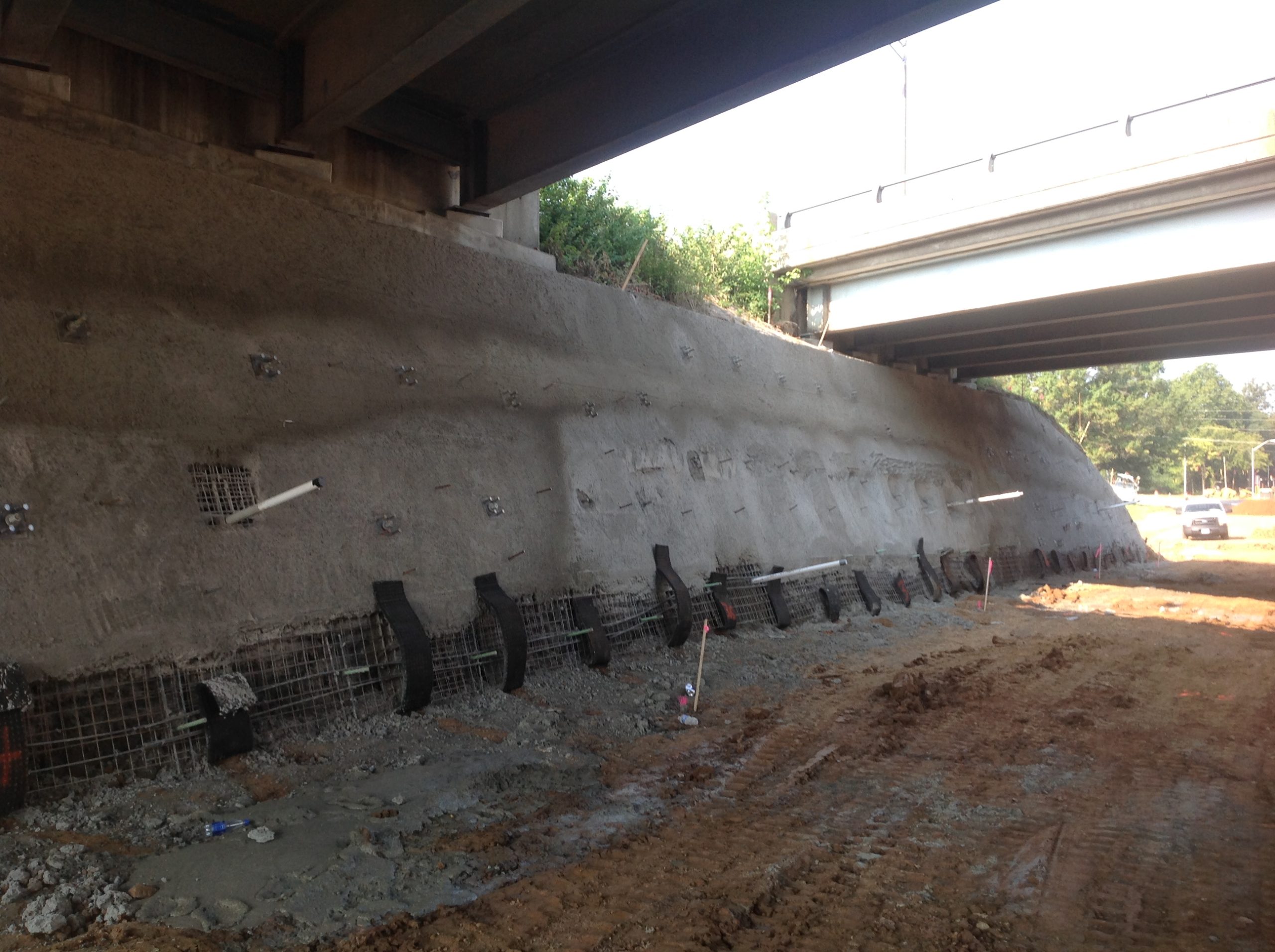
Figure 6. Soil nailing bridge approach embankment slope to provide room for roadway widening under the bridges.
- Gabion – Gabion walls are a form of gravity walls consisting of stone-filled baskets that are stacked and arranged in a manner to create a wall. The baskets are usually tied together in some manner to create a monolithic wall. Gabion walls are best suited to heights of 18 ft or less, but KYTC limits gabion wall heights to a maximum of 12 ft unless a special design is performed. Gabion walls usually require more wall face batter than other retaining wall faces to achieve stability since the stone fill is somewhat lighter than concrete. Gabion walls can be used in many situations, but they are well suited to applications where the walls may be subjected to erosion forces or water flow. Since the baskets are filled with stone, a geotextile fabric is needed between the retained soil and gabion wall to prevent loss of soil behind the wall. Standard Drawing RGX050 shows KYTC’s standard design for gabion walls up to 12 ft tall.
- Large block – Large block walls consist of stacked individual blocks of concrete that are of significant size and weight (Figure 7). These blocks have interlocking features to help provide stability and prevent sliding between the blocks when they are stacked. These walls function in a similar fashion to standard gravity walls due to their size and weight. While reinforcement can be placed in the backfill of these walls to create a MSE wall, it is not currently allowed by KYTC. Large block walls without reinforced backfill can be used as an alternative to a standard gravity wall (see Standard Drawing BGX024) if a special design is performed.
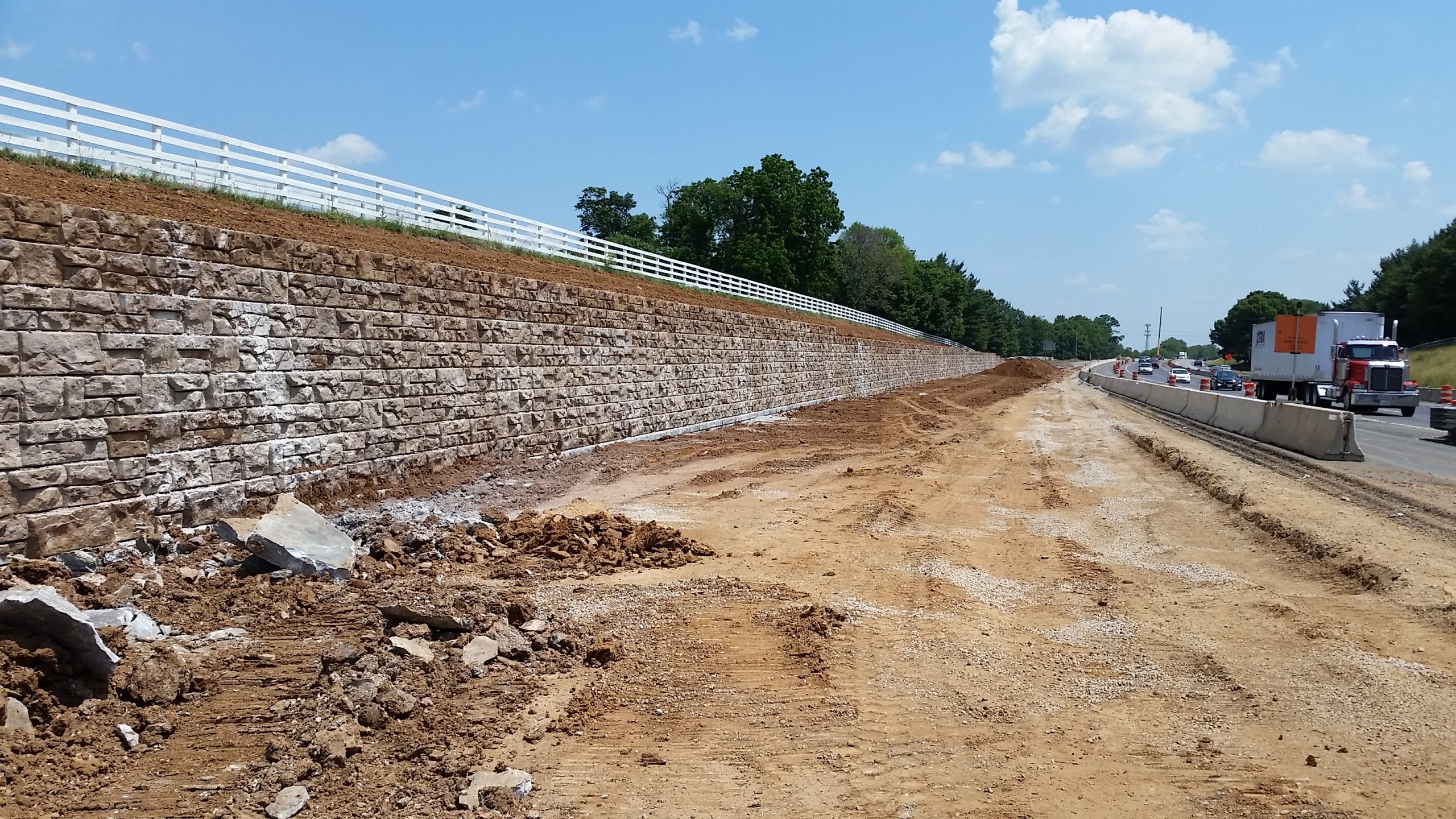
Figure 7. Large block wall on KY 4 in Fayette County, Kentucky
- Reinforced soil slopes – While not technically a retaining wall, reinforced soil slopes allow the use of steeper embankment slopes (up to a 70° slope) than if unreinforced. Reinforcement, typically a geosynthetic like a geogrid, is placed horizontally within the fill at specified spacings. The fill material is often a granular material, but soil like materials can be used if careful construction procedures are followed. Since the slopes are steeper than normal, erosion control, surface drainage control, vegetation establishment, and/or facing elements are essential to stabilize the slope face.
Figure 8 shows common wall types used by KYTC.
Most bedrock found in Kentucky consists of sedimentary rocks. Limestones, sandstones, shales, coal, and mixtures of these rocks are found across the state. In general, the bedrock across Kentucky is nearly horizontally bedded, but dipping bedrock can be found in some locations (e.g., Pine Mountain). To achieve the needed lines and grades for planned highways, excavation of bedrock is commonly required.
KYTC’s geologists carefully evaluate the bedrock and design rock slopes to provide slopes that are less prone to rockfalls while minimizing excavation when possible. The angle of rock slopes is set based on the bedrock type as well as patterns of the joints in the bedrock. On taller rock slopes, benches may be set in the bedrock. Benches are often located where bedrock formations change, and these benches help to minimize rockfalls due to differential weathering between bedrock formations (i.e., a softer rock more susceptible to weathering underlies a more resistance bedrock). Benches may also be set at locations in very tall rock slopes where the depth of drilling for blasting holes would exceed the equipment’s capacity. See Figure 9 for an example of a rock cut design.
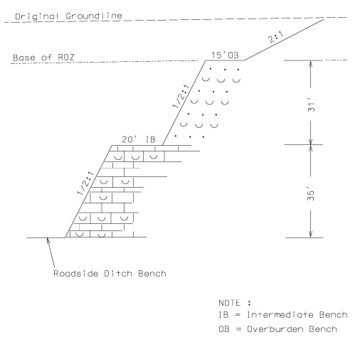
Figure 9. Typical rock slope configuration - shaley limestone or sandstone (KYTC Geotechnical Guidance Manual)
Pre-splitting is a common practice for rock slopes in Kentucky (see Section 204.03.04 of the Standard Specifications). A series of holes are drilled along the expected rock slope face. Light blast charges are placed in a portion of these holes. When the blast is set off, it causes the rock to “split” along the face in a smoother fashion than would if just using a main blast. This smoother face is less susceptible to rockfalls. After the pre-splitting, the main blast can then be set off to break up the bedrock to be excavated.
Other methods can also be included in rock slope designs to help protect roadway users from rockfalls. These include catch ditches, catch fences, draped mesh, and rockfall barriers. Please see the Highway Knowledge Portal article Rock Slopes and Rockfalls for more information on the geology of Kentucky, types of rock slope movement, and rock slope stabilization measures.
Proper placement and compaction of pavement subgrades play a vital role in performance of pavement structures. Subgrade materials not placed at the appropriate moisture content and density typically have lower strength, are more susceptible to changes in moisture content, and are more sensitive to shrinkage, swell, and freeze-thaw impacts. These items in turn directly impact the performance and life cycle of the entire pavement structure. Poorly constructed subgrades may not even have sufficient strength to support construction equipment and the remainder of pavement construction without rutting. Section 207 of the Standard Specifications provides information on construction of subgrades.
Subgrade materials often consist of materials from roadway excavation (or borrow). In Kentucky, these are commonly clayey soils or excavated bedrock materials. Bedrock materials range from durable limestones and sandstones with higher strengths to non-durable shales that break down into weaker soil-like material when exposed to water. In some instances, quarry run aggregates may be specified for rock roadbed where durable limestones or sandstones are not available from roadway excavation. A separation geotextile is commonly specified to separate rock roadbed from the underlying soil subgrade.
Where rock roadbed material is not readily available, stabilized subgrade may be specified (see Section 208 of the Standard Specifications). For stabilized subgrade, lime or cement is mixed into the subgrade soils and then compacted (Figure 10). Lime is typically used for clayey soils, and cement is used for silty to sandy soils. After a curing period, stabilized soils exhibit higher strengths and less susceptibility to moisture changes. This in turn creates a more stable platform for the construction of the remaining pavement layers as well as improving long-term performance of the completed pavement.
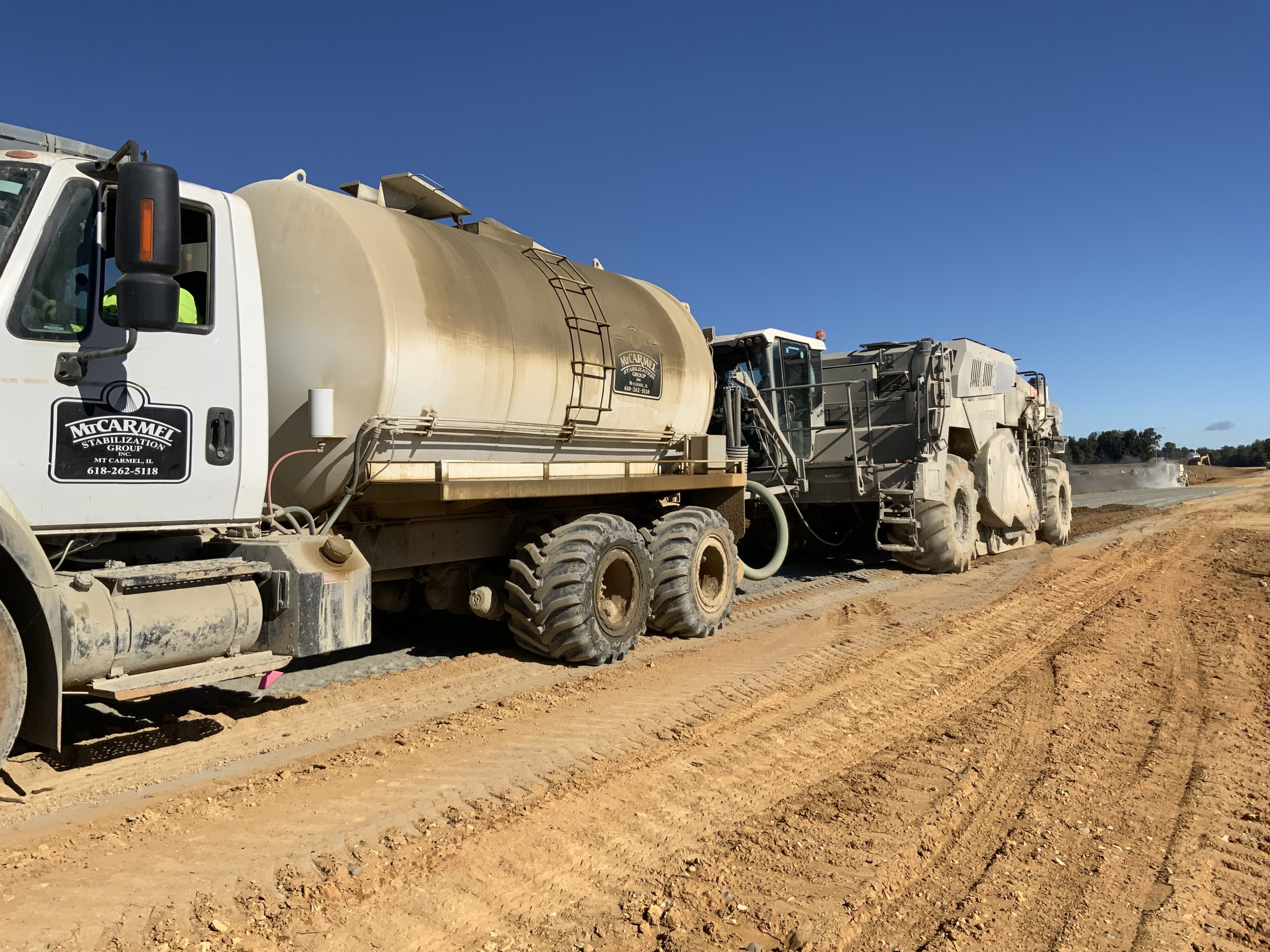
Figure 10. Mixing stabilizing materials into soil subgrade
Drainage layers, both bound and unbound, may be included in the pavement design. These layers serve to remove any water infiltration that would saturate and soften the subgrade. Drainage layers can be “daylighted” so that they drain by gravity without any other drainage features. In other cases, the drainage layers may be tied into pavement edge drains which contain perforated pipes to drain the water to appropriate outlets.
Instrumentation, monitoring, and testing may be specified on projects to ensure that construction can proceed safely, efficiently, and cost-effectively. These include but are not limited to the following situations:
- Embankment construction is over saturated or soft ground, and the rate of fill placement must be controlled to prevent failure.
- Settlement of embankments must be near completion before other construction processes such as pile driving are allowed to prevent structural damage or excessive displacements.
- Landslides or rockfalls are possible and there is a need to monitor the amount and rate of movement.
Typical instrumentation installed on construction projects include the following:
- Settlement platforms or gauges – These devices are used to determine the amount and rate of settlement of original ground under an applied load such as an embankment or a retaining wall. This information is used to control the rate of fill construction or to determine when it is safe to drive piles.
- Piezometers and groundwater monitoring wells – These devices are used to determine groundwater levels and pressures within a soil layer. Several piezometers may be installed at a specific location at various depths. Piezometers are frequently installed in conjunction with settlement plates as the dissipation of groundwater pressures is directly related to the rate of settlement. Observation wells are typically PVC pipes with slots or holes installed in a borehole to measure groundwater levels.
- Slope Inclinometers – These devices are used to monitor subsurface movement such as landslides. The measure the location of failure surfaces, the amount of movement, and rate of movement. They can also be mounted on retaining walls to detect tilting or movement of the wall.
- Tiltmeters – These devices are used to measure rotation and deflection of structures in a vertical plane. They are often installed on bridge abutments, piers, and retaining walls where rotational movement is suspected.
See the Highway Knowledge Portal article Subsurface Investigation Tools and Techniques for more information on instrumentation and monitoring tools used by KYTC.
The physiography and geology of Kentucky create the potential for geohazards. These geohazards impact all types of infrastructure including highways and bridges. If not properly addressed, geohazards can result in issues constructing, operating, and maintaining transportation facilities. Refer to the article Kentucky Geohazards and Their Impacts to Highways and Bridges for more detailed information about the location and impact of geohazards. Plans and specifications will often have geotechnical recommendations for addressing the following geohazards:
- Karst including sinkholes, caves, and springs
- Dipping bedrock and faults
- Landslides and rockfalls
- Mining and fuel extraction sites including mine openings, mine spoil, and wells
- Black shale disposal and remediation
- Scour and stream migration
Drawings, special notes, and plans notes will be included in the construction documents outlining methods for addressing these hazards. Although efforts are made during the design process to identify and address hazards, the potential for unexpected hazards to be identified during construction or even operation of a facility still exists. KYTC Geotechnical personnel should be contacted to assist when these issues arise to assist with assessing and remedying the hazard.
Construction of some geotechnical features requires the use of specialty contractors as the feature requires the use of equipment or technology that is not common or available to heavy construction contractors. Specialty contractors typically perform construction, either as a subcontractor or prime contractor depending on the nature of the project, of the following features:
- Drilled Shafts
- Drilled Shaft Integrity Testing such as CSL, Thermal Integrity Profiling, etc.
- Micropiles
- Soil Nail Walls
- Tieback Walls
- Subgrade Stabilization
- Dynamic Pile Monitoring
- Pile or Drilled Shaft Load Testing
- Rock Slope Stabilization such as catch fences, drapes, attenuation devices, rock bolting, and rock slope scaling
Less common specialty items include the following:
- Aggregate Piers – Aggregate piers consist of compacted aggregate columns installed into foundation soils. Aggregate piers can be constructed by displacing the foundation soils and placing aggregate (stone columns) or by excavating the soil by drilling, filling, and compacting the aggregate (rammed aggregate piers). The aggregate piers are stiffer than the surrounding foundation soils and result in improved bearing capacity and settlement control for embankments, retaining walls, and footings.
- Rigid Inclusions – Rigid inclusions are like aggregate piers except they include cement, concrete, or grout to produce a stiffer inclusion than aggregate. They are ideal for settlement control for embankments or structures underlain by soft soil deposits. They help transfer the load from the embankment or structure through soft soil to deeper, competent bearing soils. They are different from piles in that they are not directly connected to the structure.
- Lightweight fills – Lightweight fills typically consist of low-density cellular (foamed) concrete, geofoam blocks (Figure 11), or lightweight aggregates (expanded shales or foamed glass aggregates). Placement of low-density cellular concrete usually requires specific equipment to create and transport the foamed concrete to the placement location. Geofoam blocks and lightweight aggregates can often be placed by general contractors, but it is helpful to have manufacturer representatives on site during initial installation to assist the contractor in proper construction practices for these materials.
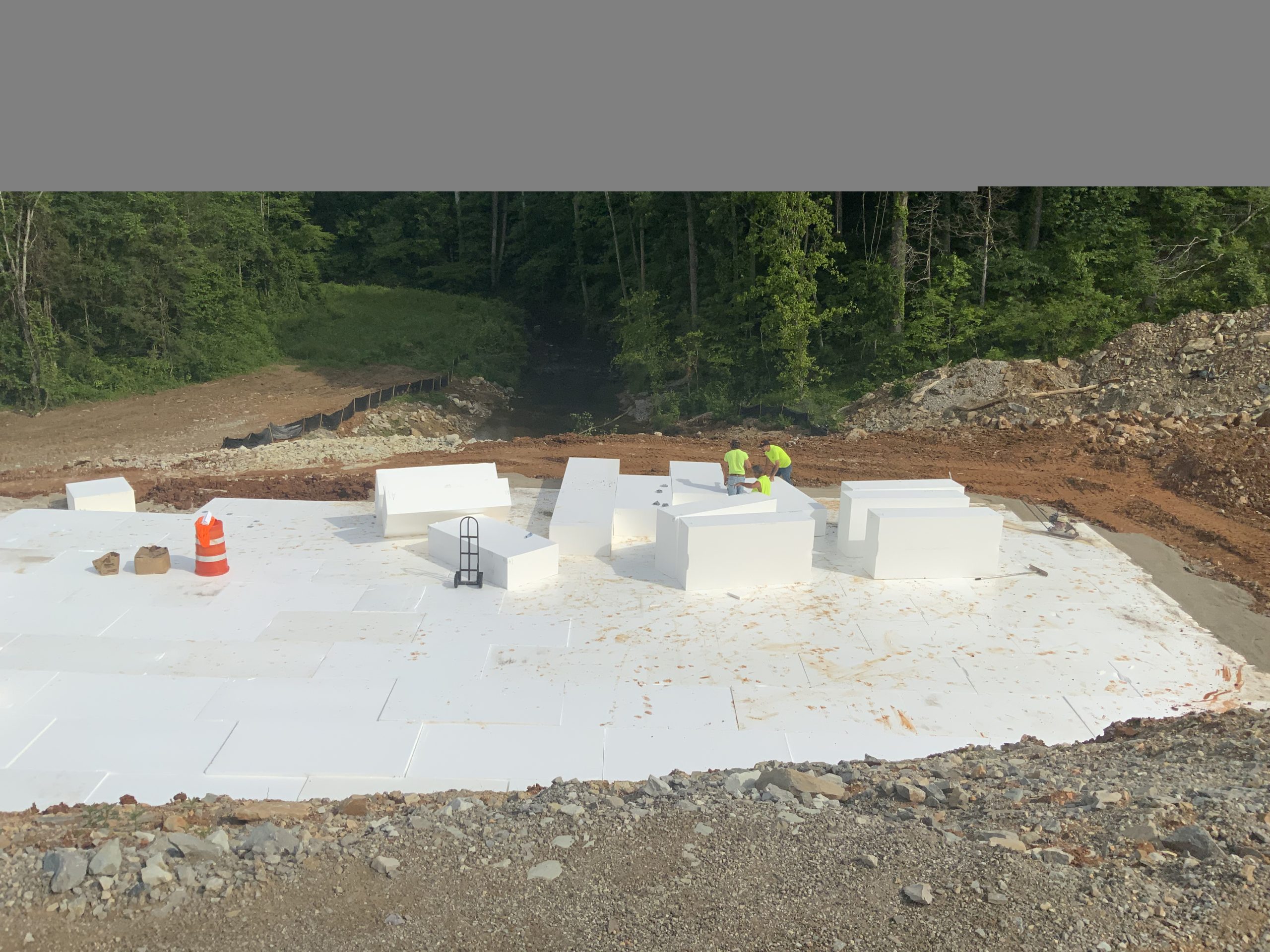
Figure 11. Installing lightweight geofoam blocks
Some specialty construction items can be installed by a general contractor, but it may be required or helpful to have manufacturer representatives on site during construction to assist the contractor in proper construction techniques for the technology. These specialty items often include:
- MSE Walls – MSE walls typically have some proprietary technology. While placement of the panels, reinforcement, and compaction of the backfill can be conducted by the general contractor, there may be specific construction techniques required by the wall manufacturer to ensure proper performance of the wall.
- Reinforced Soil Slopes – Proper placement of geosynthetic reinforcement and compaction of the reinforced fill is essential to proper performance of reinforced soil slopes. Manufacturer representatives can aid the contractor in properly placing the reinforcement, placing of fill on the reinforcement, and compacting the fill. Improper placement and compaction of the fill can result in damage to the reinforcement and reduced performance (slope failure, excessive displacements, and/or increased maintenance) of the reinforced slope.
Construction assistance is available from the Division of Structural Design Geotechnical Services Branch. This is particularly helpful for project delivery and preservation personnel who are directly involved in construction inspection activities but who may not be familiar with construction processes and required inspection items associated with a particular construction item or process. Geotechnical personnel can also assist with developing solutions to problems that arise during construction.
Geotechnical Topics Knowledge Book:
Access the complete Knowledge Book here: Geotechnical Topics Knowledge Book
Next Article: Geotechnical Aspects of Highway Maintenance
Previous Article: Subsurface Investigation Tools and Techniques

