Search for articles or browse our knowledge portal by topic.
Geotechnical Investigations – Where to Begin and How to Proceed
1.1 Definition of Geotechnical Engineering
Geotechnical engineering encompasses the acquisition, interpretation, and application of the knowledge of materials of the earth’s crust to solve civil engineering problems. It draws on knowledge from the fields of soil mechanics, rock mechanics, engineering geology, geophysics, and other related sciences.
1.2 Function and Organization of the Division of Structural Design, Geotechnical Branches
The Geotechnical Branches within the Division of Structural Design are responsible for all functions related to geotechnical engineering (except for research) required for the planning, design, construction, and maintenance of roads and bridges under the jurisdiction of KYTC’s Department of Highways.
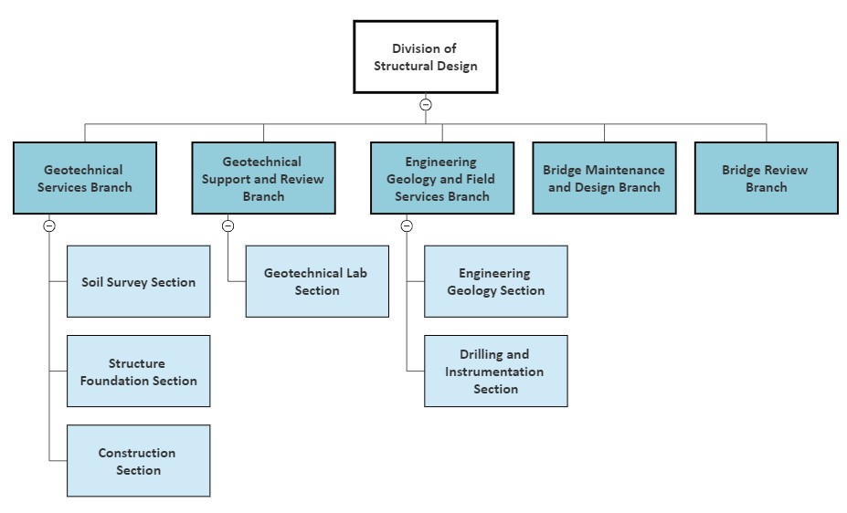
While Cabinet personnel and documents may refer to a singular Geotechnical Branch, the Branch is now divided into three separate branches (see Table 1 and Figure 1).
| Table 1. Responsibilities of Geotechnical Branches | |
|---|---|
| Branch | Function |
| Geotechnical Services Branch |
|
| Geotechnical Support and Review Branch |
|
| Engineering Geology and Field Services Branch |
|
1.3 Purpose of a Geotechnical Investigation
A geotechnical investigation furnishes information used to develop an optimal geotechnical design, one that eliminates overconservative design parameters and minimizes instances of under design. Overconservative designs increase project costs without significant benefits. Under design can result in failures that delay a project, increase construction costs, increase the difficulty and cost of maintenance, and potentially endanger the public. Optimizing designs produces an acceptable balance between costs and risk.
1.4 Limits of Investigation
Unlike steel, concrete, and other engineered materials, in situ soil and rock do not neatly conform to standards. Nor do they have homogeneous characteristics. Soil and rock properties vary across a project site, and sometimes variations can be very significant. Since these materials are below the earth’s surface and not readily visible, defects or anomalies can be hidden even from the most thorough investigation.
Drilling typically provides coverage for 0.01% or less of a project’s surface area. Only where a boring is taken do engineers have certainty about subsurface features. Understanding the characteristics of areas not captured by borings requires interpretation, interpolation, and inference. While other subsurface investigation techniques can fill in knowledge gaps, use of these methods must be balanced with budget, time, and benefit concerns. Therefore, the experience, knowledge, and judgement of the geotechnical professional is essential to understand subsurface data and provide guidance that reduces project risk.
2.1 Planning
Geotechnical overviews for planning studies address issues that may affect early transportation decisions within a project area, including:
- Problematic geologic formations and soil types
- Known geohazards (e.g., springs, landslides, mines, karst, faulted strata, acidic shale)
- Availability of suitable materials from excavation to use in subgrade and embankments
- Issues with cut and fill slopes that impact right-of-way needs
- Structure foundation types
- Pavement subgrades and stabilization requirements
Investigations for these overviews typically consist of a desk review of geologic mapping and previous geotechnical studies in the project area along with a field reconnaissance of surface conditions (see Figure 2). In some cases, a limited number of borings may be taken to provide more in-depth information. These overviews help designers evaluate alternatives, mitigation options, right-of-way impacts, environmental impacts, and project costs.
2.2 Roadway
Roadway investigations address geotechnical issues involved with constructing a highway project’s line and grade, including the design of rock and soil cuts, embankments, subgrades, geohazard mitigation, and construction recommendations.
Roadway investigations typically include drilling or other subsurface investigation methods, sampling, field instrumentation, lab testing, engineering analyses, development of plan sheets, development of construction recommendations, and report development.
A geotechnical roadway report guides the setting of rock and soil slopes and thus establishes right-of-way needs, earthwork quantities, pavement design, and other items necessary to construct a roadway. See the Geotechnical Investigation section of the Highway Knowledge Portal article Project Time Management: Final Design Phase.
2.3 Structures
Structure investigations evaluate foundations for bridges, culverts, retaining walls, and noise barrier walls, including assessments of:
- Appropriate foundation types
- Foundation capacity
- Culvert and wall bearing
- Appropriate retaining wall types
- Settlement
- Scour
- Approach embankment stability
- Slope protection
- Instrumentation or construction procedures necessary for a safe and economical foundation design
Structure investigations typically include drilling or other subsurface investigation methods, sampling, field instrumentation, lab testing, engineering analyses, development of plan sheets, development of construction recommendations, and report development.
A structure foundation report guides the selection of foundation or wall types and provides foundation recommendations, plan sheets, and construction notes necessary for structure plan development.
2.4 Construction
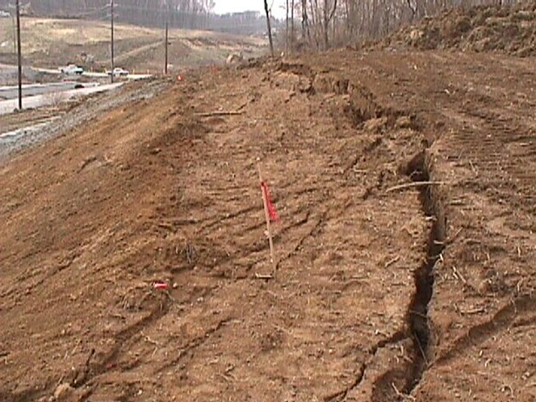
When geotechnical issues arise during construction, investigations are usually initiated by the District Project Delivery and Preservation Branch Manager or Section Engineer. Investigations typically address problems with landslides (see Figure 3), rock cuts, subgrades, excess material or borrow sites, structure foundations, or retaining walls but can focus on other items. The extent of these investigations ranges from a site visit to a full investigation with drilling, sampling, lab testing, and instrumentation.
Construction investigation reports include plans, recommendations, notes, or other items to address the issue at hand.
2.5 Maintenance
When geotechnical problems occur during operation of a roadway or structure, investigations are usually initiated by the Chief District Engineer, the Director of the Division of Maintenance, the District Project Delivery and Preservation Manager, or their designated representatives.
Landslides or rock cut problems are the most common maintenance issues, but staff also request assistance to address subgrade problems, structure problems, settlement issues, mine subsidence, caves, sinkholes, and other types of roadway or structure distress.
The extent of maintenance investigations ranges from a site visit to a full investigation with drilling, sampling, lab testing, and instrumentation. Maintenance investigations reports include plans, recommendations, notes, or other items needed to aid maintenance forces in correcting the problem.
In some cases, maintenance forces do not have the capacity to correct a problem. When this occurs, either a force contract or a contract letting is needed to obtain the resources necessary to correct an issue.
2.6 Permits
The Permits Branch may request a review for right-of-way or mining encroachment permits. The extent of the geotechnical investigation for encroachment permits typically consists of a desk review of geologic mapping and previous geotechnical studies accompanied by a site inspection. In unusual cases a more complete investigation with drilling, sampling, lab testing, and instrumentation may be required to fully understand the permit’s impacts.
In some cases, the party requesting the permit may be asked to provide additional information or to conduct a geotechnical investigation prior to permit review and approval. Reports for encroachment permits address construction practices, hazards to roadway facilities, mitigation measures, risk to the travelling public, and any other items that may impact the decision to approve a permit.
2.7 Other
Requests for other types of investigation sometimes arise. Occasionally foundation investigations for KYTC-owned facilities are requested (i.e., a new maintenance barn or section office). Other government agencies may request assistance with their facilities where their in-house staff may not have the expertise or equipment required to evaluate the problem (e.g., a dam, roadway, or bridge not owned by the Cabinet where public safety may be compromised). The extent of the involvement, investigation, and reporting for these studies varies.
The Project Manager should consult with the Geotechnical Services Branch early in project development to determine the level of geotechnical investigation required for a project as well as whether the geotechnical work will be performed by KYTC staff or by consultant. The scope of geotechnical work varies from advisory to a full-scale geotechnical investigation. Geotechnical information sought early in the process can be helpful to the Project Manager’s decision making. The Highway Design and Drainage Guidance Manuals also provide information on the level of geotechnical investigation appropriate for a project.
3.1 Project Schedule
Traditionally, the geotechnical investigation begins after Preliminary Line and Grade when the alignment has been selected. Requests for a geotechnical investigation for structures often lags Preliminary Line and Grade (i.e., Preliminary or Advance Folder stage) so that structures can be appropriately sized and substructure locations determined. Some geotechnical information can be provided earlier in the process to aid the Project Manager’s decision making.
Figure 4 is an abbreviated flow chart that outlines the steps in completing a geotechnical investigation. Preferably, the request for a geotechnical investigation should be received 10 months prior to Final Joint Inspection for large roadway jobs so that the geotechnical report can be issued 3 months prior to Final Joint Inspection. Investigations for bridge replacement projects typically take 3 – 4 months to complete. Project schedules vary based on project type, size, workload, weather, and design changes. If the Project Manager has specific concerns about project schedules, they should inform the Geotechnical Services Branch Manager, who can evaluate whether consultant services are needed to complete the investigation.
Figure 4. Abbreviated Geotechnical Workflow Chart
3.2 Submittal Requirements
All geotechnical requests are to be submitted to the Geotechnical Services Branch.
Section 200 of the Geotechnical Guidance Manual lists submittal requirements to initiate a geotechnical investigation. The Division of Structural Design Policy web page also posts updated interim versions and transmittal memos related to the Geotechnical Guidance Manual.
Submittal requirements vary by project phase. Failure to provide the required information can delay a project. In general, the submittal must include an electronic plan, profile, and cross-section files. A half-size set of paper plans is required for use in the field by drill crews. A KMZ file of the roadway alignment is helpful as field crews with mobile devices can use them to find boring locations.
During the geotechnical investigation additional information may be requested, including rock quantity sheets and coordinate submission spreadsheets for staked boring locations.
Promptly submitting these items prevents delays in the investigation. For example, rock quantity sheets are needed to determine the quantity and type of excavated bedrock available for construction of embankments and subgrades. This in turn impacts setting of embankment slopes (and thus right-of-way needs) and subgrade strength (California Bearing Ratio [CBR]) for pavement designs.
3.3 Funding
Before submitting the geotechnical investigation request, the Project Manager should ensure that sufficient funding is available to complete geotechnical work. Geotechnical staff charge directly to a project, so insufficient funds can significantly delay the geotechnical investigation. Project Managers can request funding estimates from Geotechnical staff during initial project budgeting or at any time after that to ensure adequate funds are available.
3.4 Right of Entry Issues
The Project Manager should inform the Geotechnical staff of issues with right of entry to an affected property. This includes issues with acquiring right of way, concerned property owners, restricted site access, environmental concerns or hazards, utilities, and railroads.
Gaining access to railroad properties often requires a lengthy permitting process, flagmen coordination, and paying associated costs.
Sites with environmental concerns or hazards may require specialized drilling and lab services. Delays in granting access for drilling or other subsurface investigations can delay the geotechnical investigation and impact project schedules. The Project Manager should help Geotechnical staff gain access to these properties.
3.5 Traffic Control
Drilling or other subsurface investigation techniques may be necessary within an existing roadway template. In these cases, traffic control measures are needed to provide a safe working environment for Geotechnical staff. The Project Manager should determine if District staff are available to provide traffic control or if contracted traffic control services will be needed.
3.6 Surveying and Staking of Boring Locations
Geotechnical staff prepare a subsurface exploration plan that lists locations on the project where borings are needed. Prompt staking of boring locations is needed to keep projects on schedule. The Project Manager should evaluate if District surveying staff can stake borings by the requested date. For consultant design projects, staking of borings is typically included in the contract.
It is common to move borings to avoid features found in the field such as utilities, drill rig access, or in response to property owner concerns. Often the drill crew can sufficiently determine the new station, offset, and elevation of the boring if it is moved a slight distance. Occasionally, it is necessary to have the survey crew return to the field and obtain the needed information for a moved boring. In other cases, the designer may only have to recalculate the coordinates for a moved boring.
Promptly resubmitting information for the moved borings — whether resurveyed locations or recalculated coordinates — is necessary for accurate geotechnical analyses and to maintain project schedules.
3.7 Consultant Contracts for Drilling, Lab, and Engineering Services
Early in project development, the Project Manager should discuss with the Geotechnical Services Branch whether KYTC staff or a consultant will perform the geotechnical investigation. For projects being advertised for consultant services, this decision is typically included in the advertisement and lets a consultant to include the Geotechnical consultant information in their proposal.
The Geotechnical Branches have statewide consultants for drilling, lab, and engineering services that can be used to help manage workload and schedules. In these cases, the project begins as a Department of Highways project and a decision is made later in the project to use the Statewide Geotechnical Contracts for all or part of the work. This decision is based on constraints, including schedule and work capacity of the Geotechnical Branch.
A geotechnical investigation involves several steps, each of which is described below.
4.1 Existing Information Review
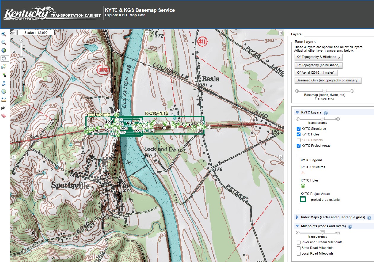
The first step is determining what information is available. This is typically a desk review that involves evaluating the roadway alignment against known geologic mapping such as geologic formations and mining. Geotechnical staff also look in the Geotechnical Projects Database for previous studies performed in the project area (see Figure 5). Staff examine available as-built plans for existing roadways or structures to gain knowledge of geology, depths to bedrock, soil types, and foundation types. Occasionally information from as-built plans can be incorporated into a new project (e.g., a bridge widening or replacement project).
Identifying step-down culverts is a particularly important effort for roadway widening projects as these culverts may not be able to support the weight of additional embankment fill over the culvert.
4.2 Site Inspections
An important but often overlooked step of geotechnical investigations is the site inspection or field visit (see Figure 6). Inspecting terrain and existing conditions lets geotechnical staff identify potential issues that can dictate the course of subsurface investigations and project design. This includes geologic hazards like sinkholes, mining, landslides, acidic shales, springs, faulted strata, or other features. Staff can also evaluate project sites to determine if they can be accessed by drilling equipment or are amenable to other subsurface investigation techniques.
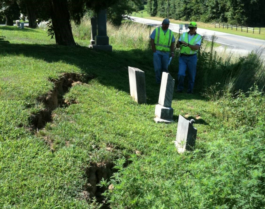
Figure 6. Site Inspection for a Maintenance Landslide
PRO TIP: A Project Manager may seek early input from Geotechnical staff before finalizing the line and grade and beginning the subsurface investigation. This is particularly true if a planning- level geotechnical report was not issued. Knowing what geotechnical hazards and concerns are present may let a Project Manager avoid problem areas, adjust line and grade, adhere to project budgets, avoid project delays, and minimize the likelihood of encountering problems later in the project development process. See the Preliminary Geotechnical Recommendations section of the Highway Knowledge Portal article Develop Preliminary Alternatives .
4.3 Subsurface Investigation
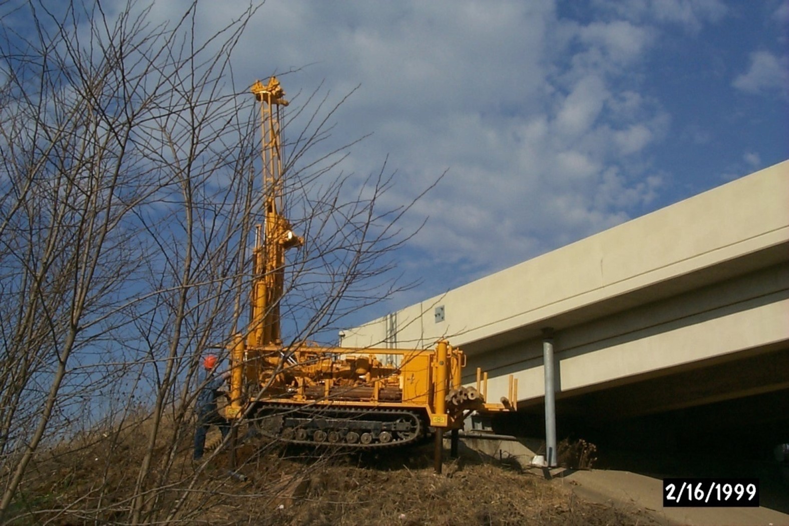
Following the review of existing information and site inspection, Geotechnical staff prepare a subsurface exploration plan. This plan includes boring locations, depths, and sample types. Once boring locations are staked, drilling and sampling are performed. Drilling may take as little as a few days for small projects and up to several months for large roadway projects (see Figure 7). In some cases, instrumentation like observation wells or slope inclinometers are installed to measure groundwater levels and slope movement. Other investigative techniques may be used as well (e.g., cone penetrometer tests (CPT), geophysical measurements, open face logging of cuts, down-hole cameras, underground lidar mapping).
4.4 Lab Testing
Soil and rock samples undergo lab evaluation (see Figure 8). Rock core samples are logged and then tested for slake durability to determine their weathering characteristics and suitability for roadway construction. Soil samples are tested to determine moisture content, classification, strength, settlement potential, CBR, and resilient modulus as needed for roadway, structure, and pavement designs. Tests like consolidation (settlement), CBR, and resilient modulus can take as long as two weeks to complete.
4.5 Analysis
Analysis begins as the drilling, rock core logging, and lab testing are completed. Typical engineering analyses for roadway projects involve rock cut slope design, soil cut slope stability, embankment stability, and subgrade evaluation. For structure projects, typical analyses include approach embankment stability (see Figure 9), shallow foundation (footing) capacity, deep foundation (piles or drilled shafts) capacity, settlement, and retaining wall stability. Analyses guide selection of project alternatives and their associated construction requirements.
During this stage a rock slope design (RSD) report may be issued along with a request for rock quantities to be calculated. The RSD report provides recommendations for rock cut design and describes geologic formations that may be encountered. These recommendations let roadway designers estimate the amount of limestone, sandstone, durable shale, and non-durable shale available on the project from excavation. These quantities are used to establish embankment configurations and soil subgrade strength parameters.
4.6 Reporting
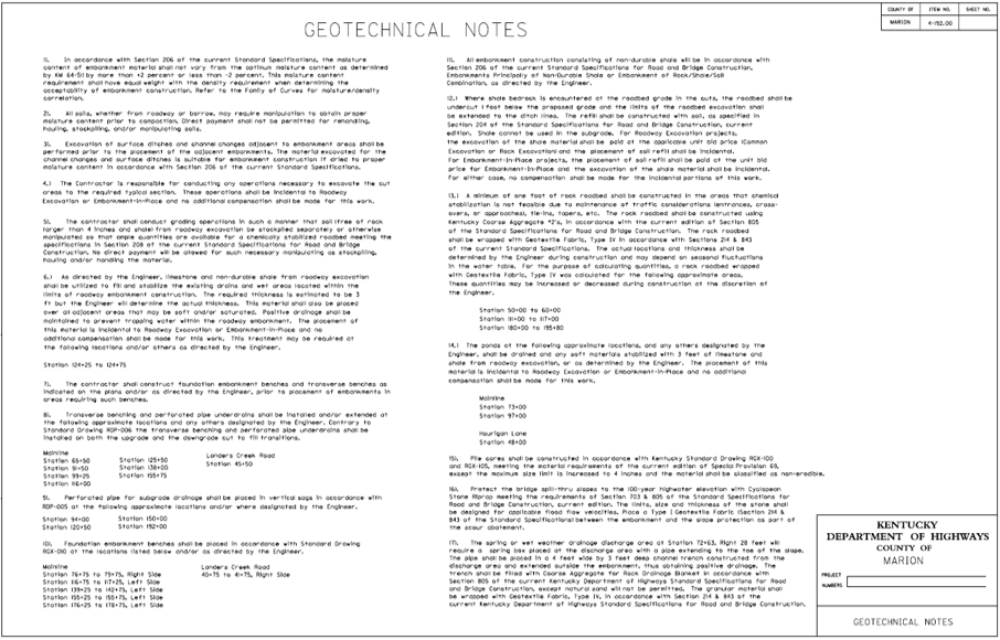
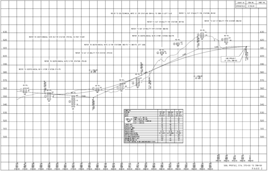
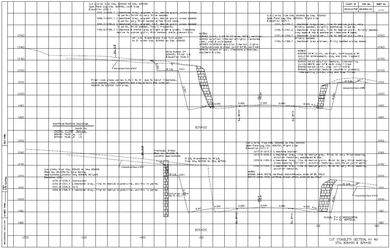
Most geotechnical reports briefly describe the project, geologic setting and conditions within the project area, drilling and sampling performed, lab testing, and engineering analyses. Following these items, alternatives, construction recommendations, and construction notes are discussed. Reports also contain drawings, which are then included in the roadway and/or structure plan sets. Examples of geotechnical drawings can be found in the appendix of the Geotechnical Guidance Manual. Drawings typically found in a geotechnical report (both paper and electronically) include:
- Geotechnical note sheets that outline construction recommendations for the selected alternatives (Figure 10). For structure projects these notes are usually only provided in the written portion of the report, and the structure designer includes pertinent geotechnical notes in the structure plan notes.
-
Subsurface investigation details that include boring locations, boring depths, sample types, groundwater measurements, geologic descriptions, and lab results (see Figure 11).
-
Special construction details for items like wick drains, foundation soil improvement, retaining walls, reinforced slopes, and other non-standard construction requirements (see Figures 14 and 15).
An abbreviated geotechnical report may be issued for roadway projects. These cases include reports produced by the Geotechnical staff, projects that are limited in size, and projects that have few geotechnical concerns. Abbreviated reports only include recommendations, geotechnical notes, and drawings.
Once a Project Manager receives a geotechnical report, they should take the following steps:
1. Review the report and apply the recommendations. Review findings and recommendations in roadway and structure geotechnical reports. There may be recommendations in the roadway report that impact the structure design and vice versa. Ensure recommendations are implemented.
2. Make sure drawings are integrated into the plan set. While rare, there have been instances of plans and proposals omitting drawings and notes from the geotechnical report. This can result in inaccurate bids, missed construction details, change orders, increased costs, and potential failures. For structures, ensure appropriate geotechnical notes are included on the structure plan notes.
3. Check for bid items and quantities that need to be included in the roadway and structure plans. Failure to include these quantities in the plans may result in inaccurate bids, change orders, and cost overruns. Some items and quantities in the structure geotechnical report may need to be included in the roadway plans. For example, a structure report may specify using crushed stone to construct an approach embankment for slope stability purposes. Embankment construction is part of the line and grade plans, and thus those requirements and quantities must be included in the roadway plans.
4. Request clarification for items that may be unclear. Discuss recommendations that are unclear or which may not be implementable with a member of the Geotechnical staff. Further discussion will clarify why a recommendation was made or may help to lead to another alternative that could be readily implemented. Dismissing a recommendation without considering possible alternatives can lead to poor performance or failure of a roadway or structure. Maintaining lines of communication between roadway designers, structure designers, and Geotechnical staff throughout the project development process can help keep projects on track, within budget, and constructable.
Many factors can impact the timing and completion of a geotechnical investigation. Common factors are listed below:
1. Changes requiring additional review or investigation. Changes to alignment and grade, number of structures, structure location, bridge span arrangements, structure foundation types, subgrade stabilization methods, or other adjustments to the preliminary plans may require a re-evaluation of the subsurface investigation plan. Additional borings, lab testing, and analysis may be required due to these changes.
2. Geohazards. The subsurface investigation may identify previously unknown geologic hazards (e.g., landslides, sinkholes, caves, springs, mines, environmental hazards, unsuitable foundation soils) that may require further drilling, lab testing, analyses, alternative development, and even changes to preliminary line and grade or structure plans.
3. Delays due to right of entry, utilities, weather. Delays in obtaining needed geotechnical information can impact project schedules. Property owners may not grant access to their properties for drilling and sampling. Drill crews may have to wait until crops have been harvested to enter a field. There may be delays in getting the necessary permits and coordinating flagmen to access railroad right of way. Poor weather conditions may not permit field activities. Unforeseen circumstances (e.g., floods) can create emergencies that require reassignment of personnel to more pressing needs.
4. Restarting projects that have been delayed or shelved. Occasionally projects are delayed or shelved for a significant period. When projects are restarted, updates to the plans and notes may be required because specifications or methods have changed. In some cases, plans may need to be updated from metric to imperial measurements. Expect some delay for restarted projects to review and update the plans and notes.
- Structural Design Policy
- Geotechnical Guidance Manual
- Geotechnical Guidance Manual Section 600, Engineering Analysis, Update (Transmittal Memorandum 19-02 dated 6-21-2019)
- Geotechnical Guidance Manual Section 604-4, Retaining Structures & Reinforced Soil Slopes, Railroad Rail Retaining Structures, Update (Transmittal Memorandum 23-01 dated 2-8-2023)
- Structural Design Manual (Interim, Transmittal Memorandum 21-01 dated 6-1-2021)
- Geotechnical Report Information
- Highway Design Guidance Manual
- Drainage Guidance Manual
- Highway Knowledge Portal Article – Develop Preliminary Alternatives
- Highway Knowledge Portal Article – Final Design Phase
© 2022
Made for the Kentucky Transportation Cabinet by the Kentucky Transportation Center at the University of Kentucky.
Disclaimer: The information contained in this knowledge base does not constitute a KYTC standard and is given for reference only. This document is to be used in conjunction with existing KYTC design and construction standards and specifications.
