Search for articles or browse our knowledge portal by topic.
Length of Need

Length of need (LON) represents the barrier length recommended to adequately shield a roadside obstacle from an errant vehicle that departs a roadway. Historically, KYTC and other agencies viewed runout length (LR) values published in the Roadside Design Guide (RDG) as excessive (AASHTO 2011). In response, agencies developed alternative methods to determine LON.
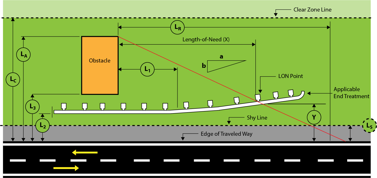
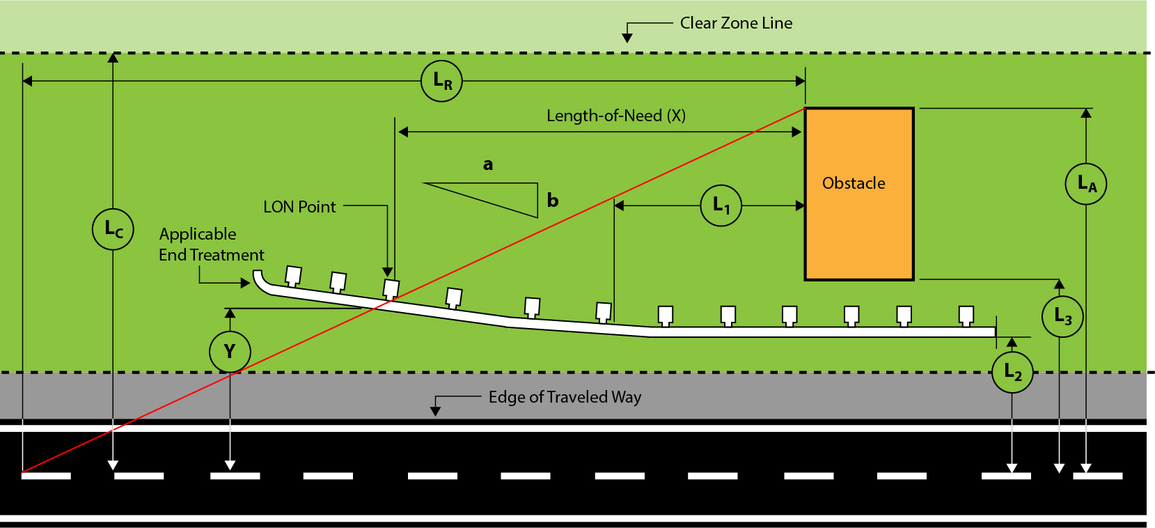
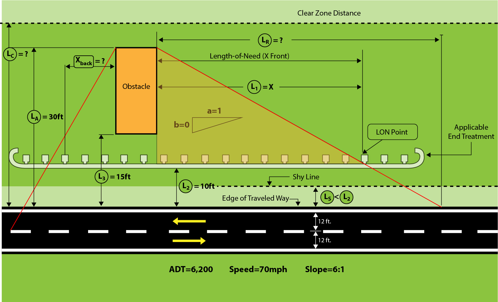
This article reviews KYTC’s method for calculating LON, defines variables typically used to calculate LON (Tables 1 and 2), provides worked examples that show how to calculate LON for adjacent and opposing traffic using KYTC’s method, and demonstrates a method to calculate barrier bid quantities. Figures 1 and 2 visualize the variables needed to calculate LON and their relationship to the roadway for adjacent and opposing traffic, respectively.
If a barrier is recommended, refer to the Highway Knowledge Portal Article Clear Zone Concept (coming soon) and Roadside Barriers – Guardrail article, KYTC Highway Design Manual (HD-800), KYTC Standard Drawings, and the RDG for information on lateral offsets, barrier deflection, terrain effects, flare rates, and length of need (LON).
| Table 1 Information Used to Determine Length of Need | |
|---|---|
| Variable | Description |
| LON (X) |
XBack refers to LON calculated for opposing traffic |
| LON Point |
|
| Y |
|
| LR |
L RBack refers to the runout length calculated for opposing traffic direction. |
| LA |
|
| LC |
|
| LS |
|
| L1 |
|
| L2 |
|
| L3 |
|
| a:b |
|
| θ |
|
| Table 2 The Roadside Design Guide's Suggested Shy-Line Offset Values | |
|---|---|
| Design Speed (mph) | Shy-Line Offset (LS) |
| 80 | 12 |
| 75 | 10 |
| 70 | 9 |
| 60 | 8 |
| 55 | 7 |
| 50 | 6.5 |
| 45 | 6 |
| 40 | 5 |
| 30 | 4 |
| Table 3 The Roadside Design Guide's Suggested Clear-Zone Distances (In Feet) From Edge of the Through Traveled Lane | |||||||
|---|---|---|---|---|---|---|---|
| Design Speed (mph) | Design ADT | Foreslopes | Backslopes | ||||
| 1V:6H or flatter | 1V:5H to 1V:4H | 1V:3H | 1V:3H | 1V:5H to 1V:4H | 1V:6H or flatter | ||
| < 40 |
Under 750c 750 - 1500 1500 - 6000 Over 6000 |
7-10 10-12 12-14 14-16 |
7-10 10-12 14-16 16-18 |
See Note b |
7-10 10-12 12-14 14-16 |
7-10 10-12 12-14 14-16 |
7-10 10-12 12-14 14-16 |
| 45 - 50 |
Under 750c 750 - 1500 1500 - 6000 Over 6000 |
10-12 14-16 16-18 20-22 |
12-14 16-20 20-26 24-28 |
See Note b |
8-10 10-12 12-14 14-16 |
8-10 12-14 14-16 18-20 |
10-12 14-16 16-18 20-22 |
| 55 |
Under 750c 750 - 1500 1500 - 6000 Over 6000 |
12-14 16-18 20-22 22-24 |
14-18 20-24 24-30 26-32a |
See Note b |
8-10 10-12 14-16 16-18 |
10-12 14-16 16-18 20-22 |
10-12 16-18 20-22 22-24 |
| 60 |
Under 750c 750 - 1500 1500 - 6000 Over 6000 |
16-18 20-24 26-30 30-32a |
20-24 26-32a 32-40a 36-44a |
See Note b |
10-12 12-14 14-18 20-22 |
12-14 16-18 18-22 24-26 |
14-16 20-22 24-26 26-28 |
| 65 - 70d |
Under 750c 750 - 1500 1500 - 6000 Over 6000 |
18-20 24-26 28-32a 30-34a |
20-26 28-36a 34-42a 38-46a |
See Note b |
10-12 12-16 16-20 22-24 |
14-16 18-20 22-24 26-30 |
14-16 20-22 26-28 28-30 |
Source: RDG July 2015 Errata (Table 3-1)
Notes
a. When a site-specific investigation indicates a high probability of continuing crashes or when such occurrences are indicated by crash history, the designer may provide clear-zone distances greater than the clear zone shown in Table 3. Clear zones may be limited to 30 feet for practicality and to provide a consistent roadway template if previous experience with similar projects or designs indicates satisfactory performance.
b. Because recovery is less likely on the unshielded, traversable 1V:3H fill slopes, fixed objects should not be present in the vicinity of the toe of these slopes. Recovery of high-speed vehicles that encroach beyond the edge of the shoulder may be expected to occur beyond the toe of slope. Determination of the width of the recovery area at the toe of slope should consider right of way availability, environmental concerns, economic factors, safety needs, and crash histories. Also, the distance between the edge of the through traveled lane and the beginning of the 1V:3H slope should influence the recovery area provided at the toe of slope. While the application may be limited by several factors, the foreslope parameters that may enter into determining a maximum desirable recovery area are illustrated in Figure 4-1. A 10-foot recovery area at the toe of slope should be provided for all traversable, non-recoverable fill slopes.
c. For roadways with low volumes, it may not be practical to apply even the minimum values found in Table 3. Refer to RDG Chapter 12 for additional considerations for low-volume roadways and RDG Chapter 10 for additional guidance for urban applications.
d. When design speeds are greater than the values provided, the designer may provide clear-zone distances greater than those shown in Table 3.
The RDG provides adjustment factors for horizontal curvature that may be applied to distances in Table 3. Table 4 reproduces these adjustment factors.
| Table 4 The Roadside Design Guide's Horizontal Curve Adjustment Factor for Clear Zones | ||||||
|---|---|---|---|---|---|---|
| Radius (ft) | Design Speed (mph) | |||||
| 40 | 45 | 50 | 55 | 65 | 70 | |
| 2950 | 1.1 | 1.1 | 1.1 | 1.2 | 1.2 | 1.2 |
| 2300 | 1.1 | 1.1 | 1.2 | 1.2 | 1.2 | 1.3 |
| 1970 | 1.1 | 1.2 | 1.2 | 1.2 | 1.3 | 1.4 |
| 1640 | 1.1 | 1.2 | 1.2 | 1.3 | 1.3 | 1.4 |
| 1475 | 1.2 | 1.2 | 1.3 | 1.3 | 1.4 | 1.5 |
| 1315 | 1.2 | 1.2 | 1.3 | 1.3 | 1.4 | - |
| 1150 | 1.2 | 1.2 | 1.3 | 1.4 | 1.5 | - |
| 985 | 1.2 | 1.3 | 1.4 | 1.5 | 1.5 | - |
| 820 | 1.3 | 1.3 | 1.4 | 1.5 | - | - |
| 660 | 1.3 | 1.4 | 1.5 | - | - | - |
| 495 | 1.4 | 1.5 | - | - | - | - |
| 330 | 1.5 | - | - | - | - | - |
Source: RDG Table 3-2
CZC=(LC)*(KCZ)
where:
CZC = Clear zone on outside of curvature, feet
LC = Clear zone distance, feet (see Table 2-1)
KCZ = Curve correction factor
Note: The clear-zone correction factor is applied to the outside of curves only. Corrections are typically made only to curves less than 2,950-ft radius.
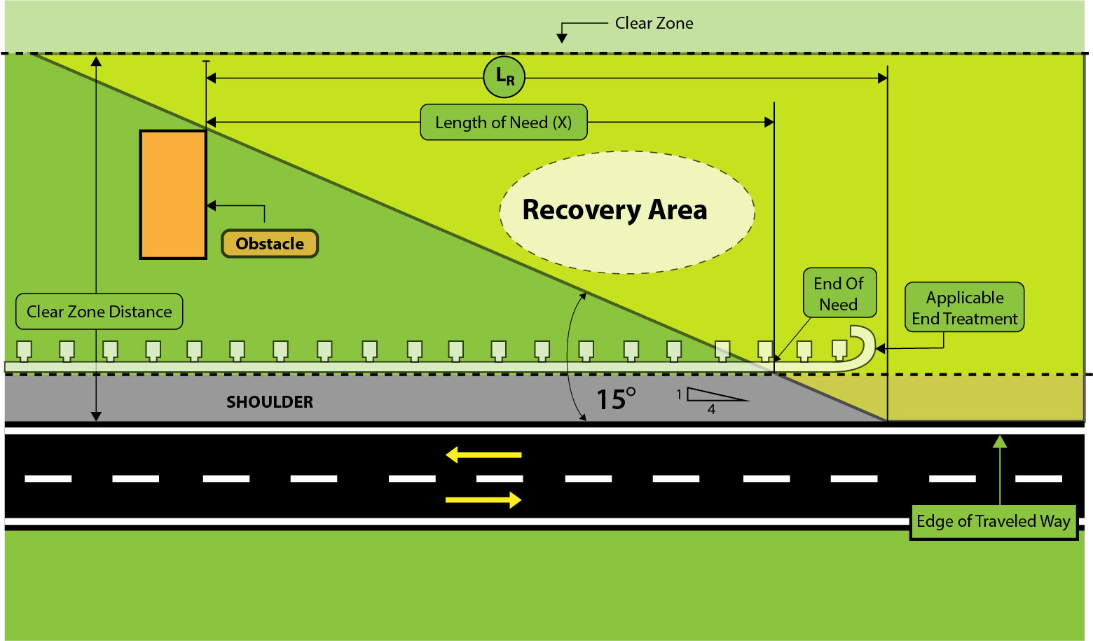
When determining where to place a roadside barrier, KYTC’s method uses a fixed vehicle departure angle of 15 degrees from the edge of the travelled way to the obstacle. This method adopts all of the variable definitions and notations presented in Table 1. Figure 4 illustrates the setup and Figure 5 is for reference, to use when calculating LON.
Problem 1a Calculating LON
Use KYTC’s method and one of the trig functions to calculate LON(X), designated XFront, for a facility that has an ADT of 6,200 veh/day, a design speed of 70 mph, and embankment slopes on the right side of the highway of 1V:6H (i.e., the side next to the adjacent traffic lane). As per KYTC’s method, θ = 15°. Assume the lateral extent of the obstacle (LA) = 30 ft and the distance from the edge of the traveled way to the guardrail face (L2) = 10 ft. Figure 6 illustrates the setup for this problem.
Step-by-Step Instructions
- Use Table 3 to determine the appropriate clear zone width (LC) based on traffic volume (6,200 veh/day), design speed (70 mph), and slope (1V:6H):
LC = 34 ft, LS = 9 ft (from Table 2), and L2= 10 ft
Since LS < L2, the barrier was placed outside the shy-line and should not be perceived as an obstacle to the driver. Refer to the definition in Table 1 and the RDG for more information concerning the shy-line.
Compare LA to LC to determine which value should be used to calculate XFront — LA = 30 ft or LC = 34 ft. In this example only one obstacle is within the clear zone (LC), and a barrier would need to shield this obstacle at the lateral distance LA. Therefore, LA will be used in the calculation.
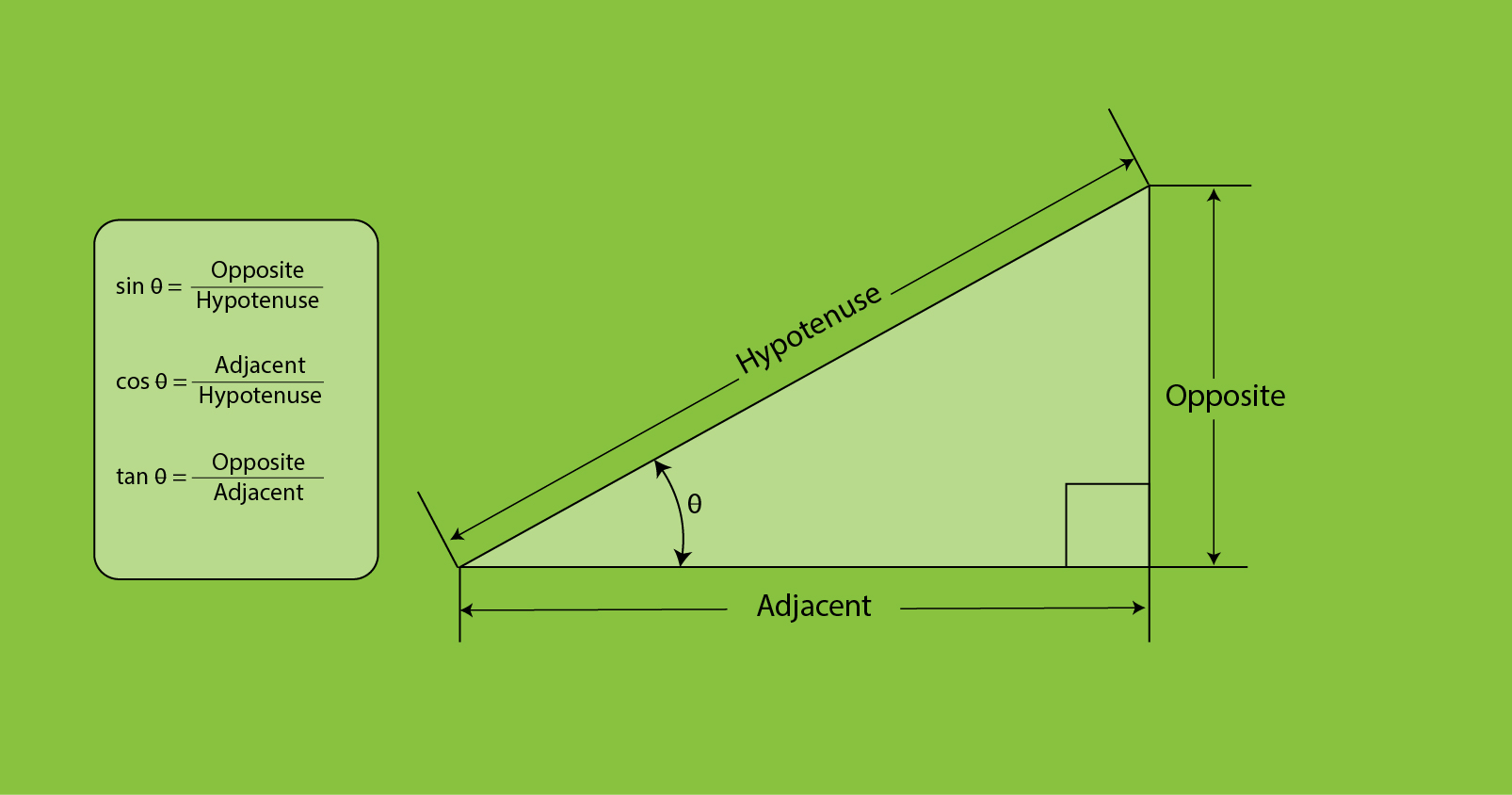
2. Select the appropriate trig function. Since information is given on LA and L2 (which is opposite of θ), use the tan function:
3. Substitute known information into the equation above. θ = 15°. Calculate the numerator by subtracting L2 from LA (or, 30 – 10):
4. Rearrange the equation to solve for XFront:
5. Simplify the equation and calculate XFront:
Solution: 
Problem 1b Calculating Runout Length
When performing the field check method (see Section 5, Conducting a LON Field Check), calculating runout length (LR) is necessary. Designers and field personnel can use this value to verify if the length of roadside shielded by a barrier is sufficient. Using the same parameters as Problem 1a, calculate LR using KYTC’s method. As per KYTC’s method, θ = 15°. The lateral extent of the area of concern (LA) = 30 ft.
Step-by-Step Instructions
1. Select the appropriate trig function. Since information is given on LA (which is opposite of θ), use the tan function:
2. Substitute known information into the equation above. θ = 15°. The numerator is LA (30):
3. Rearrange the equation to solve for LR:
4. Simplify the equation and calculate LR:
Solution: 
Problem 2a Protecting Opposing Traffic
On two-way roads, opposing traffic must also be shielded from obstacles on the opposite side of the road (i.e., the trailing end). While the same method is used to determine LON(X), all lateral dimensions are measured from the opposing traffic’s edge of traveled way which, for the driver’s side, is the highway centerline.
Use KYTC’s method and one of the trig functions to calculate LON, designated XBack , for a facility that has an ADT of 6,200 veh/day, a design speed of 70 mph, and embankment slopes on the right side of the highway of 1V:6H. As per KYTC’s method, θ = 15°. Assume the lateral extent of the area of concern (LA) = 42 ft and the distance from the edge of the traveled way to the guardrail face (L2) = 22 ft. Compared to Problems 1a and 1b, values for LA and L2 are 12 ft greater. This is because these values are measured from the centerline and the lanes have a width of 12 ft. Figure 7 illustrates the setup for this problem.
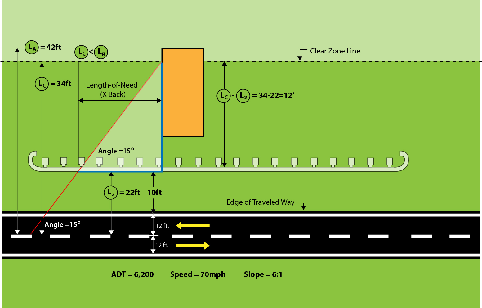
Figure 7 Setup for Example Problems 2a and 2b
Step-by-Step Instructions
- Use Table 1 to determine the appropriate clear zone width (LC) based on traffic volume (6,200 veh/day), design speed (70 mph), and slope (1V:6H):LC = 34 ft
2. Compare LA to LC to determine which value should be used to calculate XBack — LA = 42 ft or LC = 34 ft. If LA lies beyond the appropriate clear zone (LC), the designer may choose to shield only the portion within the clear zone. Because LA > LC, use LC in the calculation.
3. Select the appropriate trig function. Based on Figure 6, calculate the length of the triangle leg adjacent to θ. Since information is given on LC (which is opposite of θ), use the tan function:
4. Substitute known information into the equation above. θ = 15°. Calculate the numerator by subtracting L2 from LC (or, 34 – 22):
5. Rearrange the equation to solve for XBack:
6. Simplify the equation and calculate XBack:
Solution: 
Problem 2b Calculating Runout Length
When performing the field check method (see Section 5, Conducting a LON Field Check), a designer must calculate runout length (LR). Designers can use this value to verify that enough of the roadside is shielded by a barrier. Using the same parameters as Problem 2a, calculate the runout for the opposing traffic direction (LRBack ) using KYTC’s method. As per KYTC’s method, θ = 15°. The clear zone (LC) = 34 ft.
Step-by-Step Instructions
1. Select the appropriate trig function. Since information is given on LC (which is opposite of θ), use the tan function:
2. Substitute known information into the equation above. θ = 15°. The numerator is LC (34). Solve for LRBack, which is the denominator:
3. Rearrange the equation to solve for LRBack :
4. Simplify the equation and calculate LRBack :
Solution: 
Once a designer calculates LON for the front and back sides of an obstacle, they need to calculate the total length of guardrail. A construction note specifies this value on the plans. Guardrail length is included in the total guardrail bid item quantity.
Guardrail End Treatments (which are bid as EACH) usually include lengths of guardrail capable of redirecting an errant vehicle. This guardrail is included in and paid for by the end treatment bid item. As such, this length of guardrail is not included in the guardrail bid item quantity.
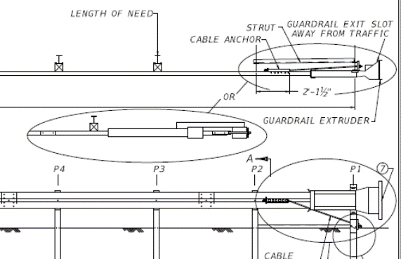
For example, KYTC’s Standard Drawing RBR-020 (Figure 4) shows a Guardrail End Treatment Type 1 has a pay limit of 50 feet and Length of Need Point at the third post. With a post spacing of 6 ft, 3 in, the total distance between the first and third posts is 12.5 ft. For a Guardrail End Treatment Type 1, the total length of redirective guardrail is 37.5 ft (arrived at by calculating 50 ft – 12.5 ft). The 37.5 ft is included in the length of the guardrail system needed to shield the obstacle, but it is not included in the length of guardrail bid quantity. See KYTC Standard Drawings for Barriers for additional information.
Problem 3 Calculating Guardrail Bid Item Quantities
Determine the guardrail bid item quantity for the example given in Figure 8. Assume that Guardrail End Treatment Type 1 will be used. Because guardrail sections are manufactured in standard lengths of 12.5 ft, when calculating quantities round up the length to the nearest multiple of 12.5 ft.
Step-by-Step Instructions
- Calculate the bid item quantity for LengthBack (which captures LON for opposing traffic)
Guardrail LengthBack = LONBack – Length of End Treatment Redirective Section
2. Substitute known information from Figure 8 into the equation above.
Guardrail LengthBack = 50 – 37.5 = 12.5 ft
3. Calculate the bid item quantity for LengthFront (which captures LON for adjacent traffic).
Guardrail LengthFront = LONFront – Length End Treatment Redirective Section
4. Substitute known information from Figure 8 into the equation above.
Guardrail LengthFront = 112.50 – 37.5 = 75 ft
5. Sum all values. Recall that the guardrail length adjacent to obstacle area = 100 ft from Figure 8. Because 12.5 ft (Step 2) and 75 ft (Step 4) are multiples of 12.5 ft, these values do not need to be rounded up.
Total Length of Guardrail = 12.5 + 100 + 75 = 187.5 ft
For this example, a typical construction note shown on the plan sheet would read: From Lt. Sta. 99+37.5 to Lt. Sta. 102+25 Construct 187.5 ft. Steel “W” Beam Guardrail (Single Face) 2- End Treatment Type 1’s.
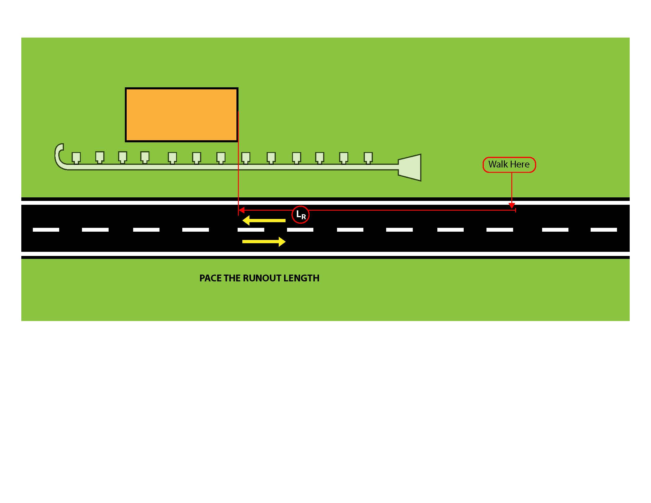
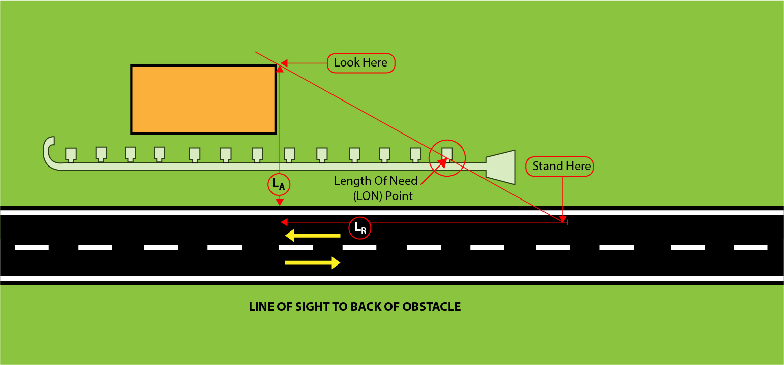
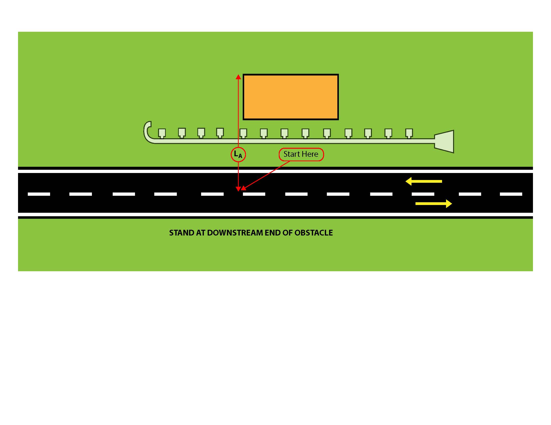
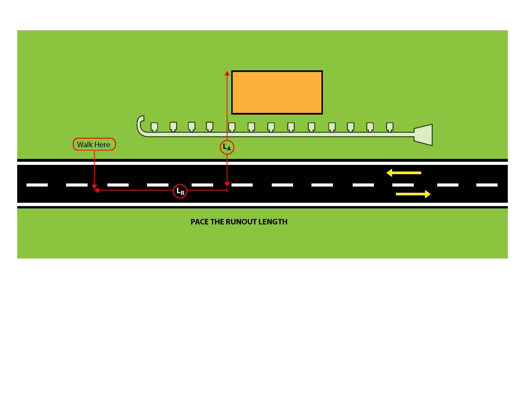
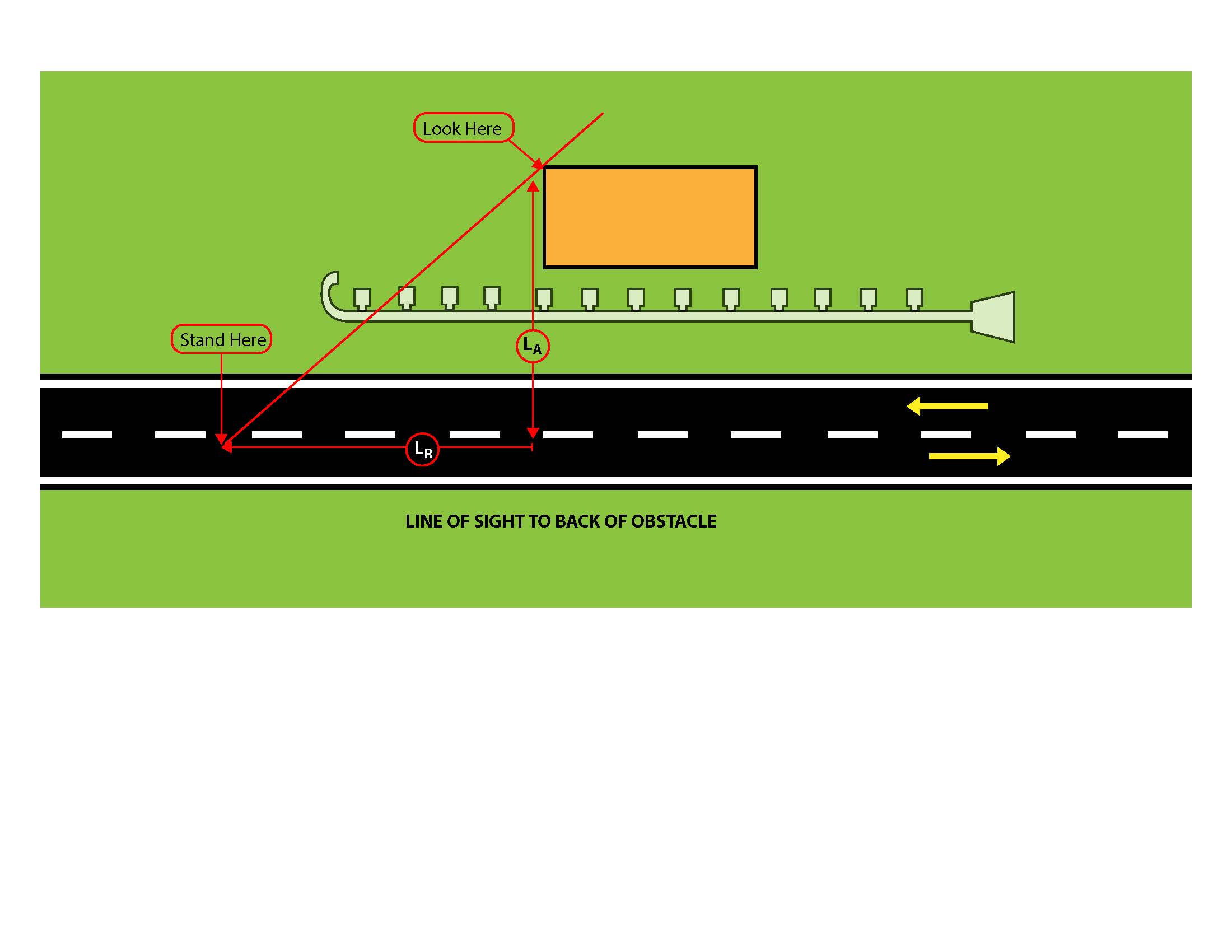
Construction Inspectors or Maintenance Personnel should perform a LON field check to verify the barrier provided is sufficiently long. The check may be performed during barrier installation while proper traffic control is in place. If done when traffic is using adjacent lanes, take proper safety precautions (e.g., wearing high visibility clothing). Each step of the process is described and illustrated below.
3. From that point, turn around and look at the back of the obstacle.
If the obstacle has no clear side, (e.g., a river or embankment), this distance may be limited to the design clear zone. If the proposed (or actual) guardrail installation crosses (or is close to) that line of sight, the area is adequately covered. If not, consider extending the barrier to shield the obstacle properly.
6. From that point, turn around and look at the back of the obstacle.
If the obstacle has no clear far side (e.g., a river or embankment), this distance may be limited to the design clear zone — as measured from the centerline. If the proposed (or actual) guardrail installation crosses (or is close to) that line of sight, the area is adequately covered. If not, consider extending the barrier to shield the obstacle properly.
Pay special attention to all obstacles in the immediate vicinity that need to be shielded. Less apparent obstacles (e.g., steep transverse embankment within the clear zone) located near an obvious obstacle (i.e., a bridge pier) should be considered when determining adequate barrier length.
KYTC guidance advises that guardrail extend at least 200 ft upstream of a fixed object. This includes the end treatment. However, the length may be reduced if field conditions warrant.
The 200 ft threshold is used to establish the minimum effective length of Strong Post W-beam guardrail (sometimes referred to as guardrail ribbon strength). Take this minimum length under consideration when calculating LON upstream and downstream of a fixed object.
Based on MASH Test Level 3 crash testing, the recommended minimum length for the standard Midwest Guardrail System (MGS) is 75 ft. Variability in roadway geometrics and/or the number and arrangement of roadside obstacles may produce LON calculations shorter than KYTC’s recommended minimum length. When the LON calculations are shorter than 200 ft, discuss site-specific considerations with the project manager and project team when making decisions about LON.
KYTC
Highway Knowledge Portal Articles
Roadside Barriers – Guardrail: https://kp.uky.edu/knowledge-portal/articles/guardrail-version-2-3/
Clear Zone Concept (coming soon)
AASHTO Roadside Design Guide (4th Edition 2011)
North Dakota DOT
-Length of Need Field Check Section
