
Search for articles or browse our knowledge portal by topic.
Pedestrian Curb Ramps

Pedestrian curb ramps are short ramps that either cut through a curb or are built up to it. Curb ramps that are soundly designed and constructed establish an accessible route from a roadway to a curbed sidewalk. They provide access to people who use wheelchairs, strollers, walkers, crutches, handcarts, and bicycles as well as pedestrians with mobility impairments (e.g., people who have trouble stepping up and down from high curbs).
The Americans with Disabilities Act (ADA) of 1990 guarantees all people — regardless of physical limitation — equal access to public facilities. Title II of the ADA defines public entities as “any state or local government and any of its departments, agencies, or other instrumentalities.” All state and local governments must comply with the ADA irrespective of whether they receive federal funds.
Any roadway project in Kentucky that entails the construction of new curb ramps or which alters existing curb ramps must follow the 2011 Pedestrian Rights-of-Way Accessibility Guidelines (PROWAG). The PROWAG covers all sidewalks located adjacent to roads on government-owned ROW. All definitions and technical specifications presented in this article are based on PROWAG requirements. References to PROWAG are indicated in parentheses — e.g., (R304.1).
This article discusses current design and installation best practices for curb ramps and will benefit KYTC designers and inspectors. While the Cabinet’s ramp Standard Drawings (RPM-170 and RPM-172) comply with PROWAG, they do not cover all potential conditions and constraints that may be encountered in the field. Where field conditions prevent strict adherence to the Standard Drawings, curb ramp installation should follow accessibility guidelines to the maximum extent feasible. The plan, design, and construction of curb ramps must be informed by user needs. Being aware of user needs and the best practices discussed in this article will equip KYTC engineers and technicians with the knowledge of how to select appropriate curb ramp types and locations within existing site constraints.
Disclaimer:
The information contained in this document does not constitute a KYTC standard and is given for reference only. This document is to be used in conjunction with existing KYTC design and construction standards and specifications.
The full definitions for terms included in this article (listed below) can be found in the HKP Glossary.
- Accessible
- ADA
- Alteration
- APS
- Blended Transition
- Clear Space
- Combined Curb Ramp
- Components
- Counter Slope
- Cross Slope
- Crosswalk
- Curb Line
- Curb Ramp
- Depressed Corner
- Detectable Warning Surfaces
- Diagonal Curb Ramp
- Element
- Facility
- Grade Break
- Gutter Flow Line (also, Curb Line)
- Landing (also, Turning Space)
- Median
- Mid-Block Crossing
- Paired Ramps
- Parallel Ramp
- Pedestrian Access Route
- Pedestrian Circulation Path
- Perpendicular Ramp
- Physical Constraints
- PROWAG
- Public Right of Way (ROW)
- Running Slope
- Secondary Pedestrian Ramp
- Structurally Impracticable
- Tactile
- Target Value
- Technically Infeasible
- Vertical Surface Discontinuities
- Standard Specification for Road and Bridge Construction
- Standard Drawings
- RPM170 and RPM172 (Type drawing # into table. Do not include dashes or spaces)
- KYTC Active Sepia List
- Per Highway Design Web Page
- List of Approved Materials
- Field Operations Guide
- Activity C802 and C990
3.1 Pedestrian Curb Ramps
It is important to recognize that every pedestrian curb ramp lying at the junction of a sidewalk and roadway intersection will have a unique configuration. There is no such thing as a standard corner. Thus, careful thought and planning must go into the design and construction of each curb ramp. This helps ensure a curb ramp fits the corner and surrounding context. KYTC’s Standard Drawings for curb ramps (RPM-170 and RPM-172) comply with PROWAG. Where conditions preclude adherence to the Standard Drawings, the design and construction of a curb ramp must be tailored to topographical and physical constraints. Moreover, they should meet — to the maximum extent feasible — accessibility requirements for ramp slope, cross slope, landings, and street connections.
PROWAG dictates the provision of pedestrian curb ramps at all existing marked and unmarked crosswalks that KYTC is responsible for. Detectable warning surfaces must be installed at all curb ramps (See Section 5.10 Detectable Warning Surfaces below).
3.2 Age of Roads and Sidewalks
Before the ADA’s passage, highway construction and maintenance activities often paid little attention to sidewalks. Pedestrian facilities and accessibility were either not addressed or done so at a minimal level. Because accessibility guidelines and requirements have — and continue to — evolve, figuring out how to make sidewalks accessible has resulted in significant confusion. Kentucky’s directive that existing pedestrian facilities must comply with PROWAG guidance helps to alleviate uncertainty. Depending on the age of the sidewalk and road, a pedestrian path may not be accessible or may have limited accessibility. KYTC is dedicated to meeting ADA requirements and plans to address curb barriers and non-compliant curb ramps. Through highway projects, the Cabinet upgrades pedestrian access and improves accessibility throughout Kentucky.
3.3 Highway Projects: New Construction
Pedestrian facilities (including curb ramps) built on newly constructed highway projects must be accessible to people with disabilities, regardless of the project’s funding source. Full compliance with accessibility requirements may be impractical where structural or topographical constraints make it physically impossible to construct facilities that are fully compliant. When constraints arise, compliance is required to the extent practicable. The PROWAG discusses how to handle situations where existing conditions make it structurally impracticable to fully comply with accessibility requirements. ADA documentation defines structurally impracticable as “unique characteristics of land that prevent the incorporation of accessibility features in a facility”.
3.4 Highway Preservation: Alteration and Maintenance Projects
Federal regulations define an alteration project as one which modifies a highway facility in the public right of way (ROW) in a manner that affects or could impact pedestrian access, circulation, or use. KYTC alteration projects must address pedestrian curb ramps. (This includes KYTC’s resurfacing program, which falls under the federal definition of an alteration. The table below provides examples of alteration and maintenance projects.) Existing curb ramps located within the limits of an alteration project must be checked for PROWAG compliance. Pedestrian curb ramps that do not meet accessibility requirements must be reconstructed (or constructed if they do not exist). Non-compliant curb ramp elements must be removed and replaced. Non-compliant elements may be kept, but only if achieving compliance is deemed technically infeasible. The sidewalk’s existing condition does not influence the decision to add a curb ramp.
When a local public agency (LPA) administers an alteration project (e.g., a streetscape) on the public ROW, all pedestrian facilities located on the project must comply with the ADA and PROWAG.
KYTC maintenance projects are not obligated to make improvements that enhance accessibility or add curb ramps. (Please note that KYTC’s resurfacing program falls under the federal definition of an alteration and must address pedestrian curb ramps.) See the ADA Requirements Flowchart and following tables for examples of maintenance and alteration projects.

| Examples of Maintenance and Alteration Projects | ||||
| Roadway Maintenance | ||||
| Filling and Sealing Cracks | Joint Repairs | Shoulder Repairs | ||
| Surface Sealing | Dowel Bar Retrofit | Pipe and Inlet Repairs | ||
| Chip, Slurry, and Fog Seals | Spot High-friction Treatment | Pulling and Restoring Ditches | ||
| Scrub Sealing | Diamond Grinding | Guardrail Repair and Installation | ||
| Joint Crack Seals | Pavement Patching | Re-striping | ||
| Roadway Alteration | ||||
| Open-graded Surface Course | Microsurfacing/Thin-lift Overlay | Widening Existing Pavement | ||
| Cape Seals | Addition of New Asphalt Layer | Addition of Turning Lanes | ||
| Mill and Fill/Mill and Overlay | Asphalt and Concrete Rehabilitation and Reconstruction | Pavement Rubblizing | ||
| Hot In-place Pavement Recycling | New Construction | Installation of New Drainage Structures to Improve Existing Drainage Charateristics | ||
| Bridge Maintenance | ||||
| All Painting of Bridge Members | Expansion Joint Repairs and Replacement | Refurbishing or Restoring Bridge Bearings | ||
| Scour Countermeasure Activities | Concrete Crack Repairs | Deck Drainage System Repairs | ||
| Seismic Retrofit Activities that do not Include Replacement of Bearings or Structural Members | ||||
| Bridge Alteration | ||||
| Bridge Deck Overlay Projects | Repairs to Strengthen Substructure Elements | Bridge Deck Replacement | ||
| Repair Structural Members to Restore or Enhance Structural Capacity | Bearing Replacement | Superstructure Replacement | ||
In 2007, The Public Rights-of-Way Access Advisory Committee (PROWAAC) issued the following statement about pedestrian curb ramps:
“The design and placement of curb ramps into existing developed streetscape is governed by many of the same considerations as roadway design: controlling horizontal and vertical geometries, surface conditions, and access to intersections, all at the scale of the pedestrian rather than the vehicle.
In an alteration, a balance needs to be struck between pedestrian and vehicle users vying for travel space within a limited right of way already constrained by existing development. A good understanding of the rationale behind accessibility standards will help the designer integrate usability for pedestrians who have disabilities into agency decision making.”
4.1 Design Guidelines for Pedestrian Curb Ramps
Because each curb ramp is unique, careful thought and planning must go into their design and construction. Use the guidelines below to comply with PROWAG requirements when selecting which type of curb ramp should be used and when deciding upon location.
1. Consider the whole intersection.
- Locate the pedestrian access route(s) for the sidewalk(s) around the intersection.
- Determine how each pedestrian access route (i.e., crosswalk) will cross the street. Confirm the crosswalk will not be blocked by stopped vehicles at a traffic control device.
- Consider pedestrian refuge islands, when they are present.
- Examine intersection corners and identify potential conflicts to building the ramp (e.g., existing utility features or restrictive ROW).
- Consider pedestrian sight distance, driver sight distance of pedestrians, and vehicle stopping locations when choosing curb cut locations.
- Consider the need for and locations of pedestrian pushbuttons at signalized intersections.
NOTE: Curb ramp installation is generally more difficult on alteration projects than on new construction projects because existing conditions (e.g., buildings, walls, sidewalk gradients, ROW width) may limit the amount of space available to provide the desired or required accessibility.
2. Locate landings for all ramps.
- On alteration projects, landings are usually the most important design control because constructing a compliant landing depends on ROW availability and how the pedestrian access route will be maintained through the corner. Identifying the landing location helps with choosing the best curb ramp option.
3. Verify the elevation difference between curb flow lines and sidewalks to confirm that an acceptable ramp grade can be built.
- The maximum ramp running slope is 8.3 percent (1V:12H or 1 inch per foot). When determining whether an acceptable ramp can be built, use a running slope target value of 7.5 percent (1V:13.3H or 0.9 inch per foot), which allows a construction tolerance of ±0.5 percent.
4. Determine which ramp works best.
- Select a curb cut type after (1) verifying it is possible to provide a landing and (2) establishing the pedestrian access route location. Generally, the hierarchy for curb ramps at intersections is:
i. Paired Perpendicular Curb Ramps – See Section 6.4
ii. Combined Perpendicular Curb Ramps – See Section 6.5
iii. Parallel Curb Ramps – See Section 6.6
iv. Secondary Parallel Curb Ramps – See Section 6.7
v. Blended Transition: Depressed Corner – See Section 6.8
vi. Blended Transition: Fan Ramps – See Section 6.9
vii. Single Direction Curb Ramps – See Section 6.10
viii. Diagonal Ramp – See Section 6.11
4.2 Intersection Consistency
Whenever possible, use the same curb ramp design at each quadrant in the intersection. Sometimes consistency is not possible and multiple designs are necessary. Keep in mind that the design which falls lowest in the design hierarchy should never serve as the controlling option. For example, if one corner requires a depressed corner because of site constraints, but the other three corners can accommodate paired perpendicular curb ramps, only use the depressed corner where it is necessary. The other three corners should adopt paired perpendicular curb ramps.
4.3 Intersection Surface Drainage
Pay careful attention to existing surface drainage conditions when designing and then building curb ramps. Debris and water diminish a curb ramp’s usability. The curb ramp and gutter connection should (1) prevent water from ponding at the base of the ramp and (2) impede debris accumulation. Ensuring that the ramp and sidewalk have positive drainage helps eliminate ponding. On new construction projects, consider adding a storm water catch basin just upstream of curb ramps.
Historically, surface drainage has been maintained at curb ramps by constructing a 1/2-inch lip at the face of the curb and the gutter flow line. But doing so compromises the ramp’s usability. Rather, provide a gradual transition between the pedestrian ramp, gutter, and street. To preserve a smooth ride for wheelchair users and other pedestrians with wheeled devices (e.g., stroller, wagon), the gutter flow line may have a maximum 1/4-inch lip vertical or a 1/2-inch lip beveled with a slope no steeper than 50 percent (1V:2H) across the entire vertical surface discontinuity.
Vertical Surface Discontinuities

Most curb ramps share common features (even if their designs differ). The following pages describe these features and include PROWAG technical requirements.


5.1 Landing (i.e., Turning Space)
Definition: Landings provide a space for users to stop, rest, and change direction on the top or bottom of a curb ramp (R304.2.1 and R304.3.1). A landing must be provided (1) at the top of perpendicular ramps, (2) at the bottom of parallel ramps, or (3) where a ramp changes direction. A landing is not required at the top of the ramp on blended transitions.
Technical Requirements
5.1a Landing Slopes: The maximum cross slope and running slope is 2.0 percent (1V:50H or 1 inch per 4 feet) (R304.2.2 and R304.3.2). For concrete placement, use a construction target value of 1.5 percent (1V:67H or inch per 4 feet) with a tolerance of ±0.5 percent. When landings are at the back of curb, cross slopes may be increased to match allowable values in the pedestrian street crossing section (R304.5.3).
5.1b Landing Size: The landing must be at least 4 feet by 4 feet. Where the landing’s turning space is constrained on at least one side, provide 5 feet in the direction of the pedestrian street crossing.
Perpendicular Curb Ramp Landing

Perpendicular Curb Ramp Length and Width
Parallel Curb Ramp Landing – Constrained Condition

Parallel Curb Ramp Landing Length and Width

5.2 Curb Ramp
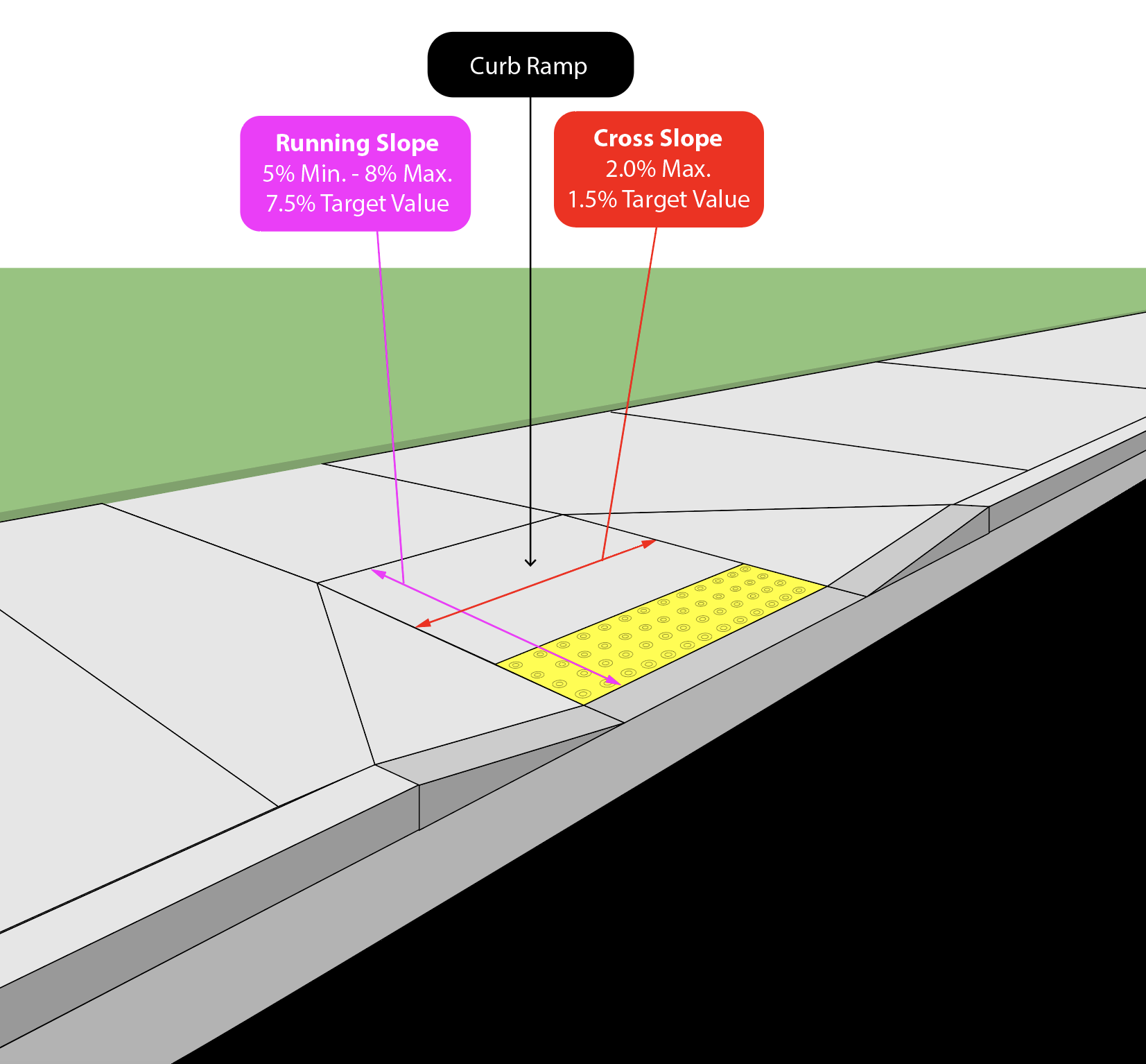
Definition: A curb ramp’s running slope is the grade measured along the direction of travel.
Technical Requirements
5.2a Ramp Running Slope: The minimum allowed running slope is 5 percent (1V:20H or 3/5 inch per foot) and the maximum is 8.3 percent (1V:12H or 1 inch per foot). If the maximum slope is needed, use a running slope target value of 7.5 percent (1V:13.3H or .9 inch per foot) to allow a construction tolerance of ±0.5 percent. Curb ramps do not have to be longer than 15 feet, regardless of the resulting slope (R304.2.2 and R304.3.2).
Note: When a sidewalk element’s running slope is less than a 5 percent, it is defined as a blended transition. Blended transitions do not require a landing at the top of the ramp, which can be beneficial.
Parallel Curb Ramp Running Slope & Cross Slope

Perpendicular Curb Ramp Running Slope & Cross Slope

A curb ramp’s cross slope is the grade measured perpendicular to the direction of travel.
5.2b Ramp Cross Slope: The maximum cross slope is 2.0 percent (1V:50H or 1 inch per 4 feet). For concrete placement, use a construction target value of 1.5 percent (1V:67H or 3⁄4 inch per 4 feet) with a tolerance of ±0.5 percent.
At intersection legs without full stop or yield control (i.e., uncontrolled) and at mid-block pedestrian crossings, curb ramp cross slope can match the cross slope in the pedestrian street crossing section. See PROWAG R304.5.3 for additional details.
When a curb ramp must tie to a steeply sloped roadway, the ramp must be transitioned from the top of the sidewalk to the roadway profile slope. Distribute this slope transition evenly along the length of the ramp. The cross slope rate of change should not exceed 3.00percent per 1′-0″.
Curb Ramp Transition to Steeply Sloped Roadway

Ramp length is based on the ramp’s running slope and vertical difference between the curb line and the top of sidewalk. Determining the appropriate length is an iterative process, but essential for achieving the correct running slope. See further discussion in Section 5.8 Tying into the Existing Sidewalk Slope.
5.2c Ramp Length: In most settings, the recommended curb ramp length is 4 feet to 6 feet. Irrespective of the resulting slope, curb ramps do not have to be longer than 15 feet (R304.2.2 and R304.3.2).

A curb ramp’s maximum width excludes curbs and flares.
5.2d Ramp Width: The minimum width for a curb ramp is 4 feet (excluding any flared sides) (R304.5.1).
5.2e Ramp Orientation: Curb ramps and/or blended transitions must connect pedestrian access routes at each pedestrian street crossing. For new construction projects, a separate curb ramp is required at each pedestrian street crossing. If possible, ramps should be aligned with the preferred path of travel — ideally, a straight line between curb ramps on opposing sides of the road.
Curb ramps can present challenges when placed on corners with large radiuses. Perpendicular ramps on a large radius are acceptable if the ramp is contained within the crosswalk it serves and if it provides a clear space at the bottom of the ramp.
Ramp Orientation


On alteration projects, follow the new construction requirements if possible. Where existing constraints prevent the installation of two curb ramps, a single diagonal curb ramp is permissible but not recommended (R207.2). Avoid single diagonal curb ramps whenever possible. One ramp servicing two crossing directions does not help pedestrians suffering from visual impairments with wayfinding. Motorists will also find it difficult to determine in which direction a pedestrian is preparing to cross.
5.3 Ramp Edges: Flared Sides or Curb Returns
Definition: Ramp edges may be either flared sides or curb returns. Concrete flares on the sides of ramp transitions connect the sidewalk and ramp edge. Flares are not a part of the pedestrian access route and do not have to adhere to accessibility dimensions.
Technical Requirements
5.3a Flare Slope: The maximum slope for flares is 10 percent (1V:10H or 1.2 inches per foot) (R304.2.3). Flares should be constructed at a slope between 8 percent (1V:12.5H or 1 inch per foot) and 10 percent (1V:10H or 1.2 inches per foot), which is sufficient to clearly define the curb ramp from the sidewalk. Pedestrians can approach the curb ramp from the side and tripping hazards are eliminated.
Ramp Edges: Flare Sides & Curb Returns

Incorrectly Flared Ramp

Curb returns may be used — in lieu of flares — if ramp sides are adjacent to turf or a landscaped surface (i.e., areas not traversed by pedestrians). To eliminate tripping hazards, the adjacent surface to a curb return should not be part of the pedestrian circulation path.
Consider using curb returns where an existing underground facility, structure, or aboveground obstruction prevents use of a flare. Doing so may yield a curb ramp that is narrow enough to fit adjacent to existing structures. Additional railing or another physical barrier may be needed to isolate this type of curb ramp and prevent trip/fall accidents at the returned curb.
5.4 Grade Breaks
Definition: Grade breaks should let users smoothly transition from the sidewalk to the ramp and from the ramp to the street. Abrupt or improperly placed grade breaks pose a tipping hazard for wheelchair users and a tripping hazard for users with vision impairments.
Improperly Placed Grade Break at Street-Ramp Interface

Technical Requirements
5.4a Perpendicular Grade Breaks: Grade breaks at the top and bottom of a curb ramp must be perpendicular to the ramp’s running slope. No grade breaks are allowed on the surface of curb ramp runs and turning spaces. Surface slopes that meet at grade breaks must be flush. Transitions from curb ramps to the gutter, street, or landing areas must free of vertical discontinuities (R304.5.2).
Perpendicular Grade Break


5.5 Level Area at the Bottom of Ramps on Large Radius Corners
Definition: On corners with large radiuses, perpendicular ramps aligned with the crosswalk (referred to as directional ramps) are often left with a triangular area at the bottom of the ramp, which should slope at 2 percent toward the gutter flow line. Creating perpendicular grade breaks at the bottom of directional curb ramps can be difficult and is often overlooked. The difficulty in achieving a level area at the bottom of a directional ramp is one reason directional ramps do not work well in many cases. Placing a curb ramp perpendicular to the back of curb/flow line may help to avoid this issue.
Level Area at Ramp Bottom


5.6 Clear Space
Definition: At the bottom of perpendicular curb ramps, provide a minimum clear space of 4-feet by 4-feet within the width of the pedestrian street crossing, but entirely outside of the parallel vehicle travel lanes. (R304.5.5)
Clear Space

5.7 Counter Slope
Definition: Wheelchair users may find it difficult to negotiate a rapid grade change along the pedestrian access route. This condition may be present between the base of a curb ramp and the street gutter. Counter slopes that are too severe may (1) prevent wheelchair footrests or anti-tip wheels from clearing the transition or (2) tip a wheelchair backwards as the user ascends the ramp.
Counter Slope

Technical Requirements
To evaluate counter slopes, the algebraic grade difference (G) of two adjacent slopes is often used:
G = g2 – g1
G is the gutter pan or crosswalk slope (g2) minus the curb ramp running slope (g1). Uphill slopes are defined as positive (+) and downhill slopes negative (-).
For curb ramps, the maximum allowable running slope is -8.3 percent. For gutter pans the maximum slope is +5.0 percent. For these values G = 13.33 percent. (R304.5.4). Changes in the path of travel should not exceed an algebraic difference of 11 percent.
If conditions warrant installation of a counter slope greater than 11 percent, provide a level strip at the bottom of the curb ramp behind the curb. The level strip must be as wide as the ramp and a minimum of 2 feet deep in the path of travel. See the illustrations below.
Counter Slope Transition


5.8 Tying into the Existing Sidewalk Slope (Chasing the Grade)
Definition: Topography of the roadway and surrounding site must be considered during curb ramp construction. If a curb ramp’s grade is less than the grade of adjacent surfaces, the ramp will not tie into the existing sidewalk. Under these conditions, curb ramp length must be adjusted to tie into an existing sidewalk while not exceeding maximum allowable grades. This is referred to as chasing the grade.
Technical Requirements
When chasing the grade, the uphill ramp is longer than it would be if it were built on level terrain, and for the proposed tie-in locations the curb ramp length should not exceed 15 feet without a landing area. Where a ramp chases the grade, providing multiple ramp runs with landing spaces located at 15-foot intervals may be an option to tie the ramp into the existing sidewalk elevation. PROWAG does not require that ramps chase the grade for more than 15 feet. A curb ramp may be limited to 15 feet and tie into the existing sidewalk irrespective of the resulting ramp running slope. When this occurs, take all feasible steps to minimize the ramp’s running slope.
The ramp connecting a downhill slope is considerably shorter than when built on level terrain. Ramps that connect into steep uphill/downhill grades should be as short as possible (8.3 percent maximum), so the approaching walk is not steeper than it needs to be.
Tying Into the Existing Sidewalk (Chasing the Grade)


| Tying into the Existing Sidewalk | ||||||
| Road Slope, S | Elevation Difference Between Points A and B | Length of Downhill Side Ramp, L1 | Length of Uphill Side Ramp, L2 | |||
| 0% | [B-A] = 6" | 6 Feet | 6 Feet | |||
| 1% | [B-A] ≤ 6 ⅞” | 5 ½ Feet | 7 Feet | |||
| 2% | [B-A] ≤ 8” | 4 ⅞ Feet | 8 Feet | |||
| 3% | [B-A] ≤ 9⅝” | 4 ½ Feet | 10 Feet | |||
| 4% | [B-A] ≤ 11¾ ” | 4 ⅛ Feet | 12 Feet | |||
| 5% + | [B-A] ≤ 15 ” | 3 ¾ Feet | 15 Feet | |||
5.9 Secondary Ramp
Definition: When existing terrain has significant elevation change, a secondary pedestrian ramp may be built away from the street corner and used to transition the sidewalk to the existing roadway curb height. A secondary ramp rising from the first ramp’s landing quite often ties into the existing sidewalk, resulting in a compliant design and usable facility. This also avoids having to build a curb ramp from the corner that chases the grade over too long a distance.
Technical Requirements
When chasing the grade to connect into the existing sidewalk, it is reasonable to extend the run of the secondary ramp up to 15 feet. If the tie into the existing sidewalk cannot be made within 30 feet of two different ramps at an 8.3 percent slope, a straight grade ramp (or secondary ramp) up to 15 feet long — and greater than the 8.3 percent maximum slope — may be constructed. This constitutes the maximum extent feasible for the site condition.
5.10 Detectable Warning Surfaces
Definition: Detectable warnings are small, truncated domes built into or applied to a walking surface that can be sensed by a cane or underfoot. On pedestrian access routes, detectable warning surfaces indicate the boundary between a pedestrian route and vehicular route. They assist traveling pedestrians that have vision impairments. While they do not serve as navigational aids (R305), detectable warning surfaces provide a visual queue to help those with vision impairment to locate the curb ramp across the street. Accordingly, detectable warning surfaces must contrast visually (light on dark or dark on light) from the surrounding paved surfaces (R305.1.3).
Technical Requirements
5.10a Location: Detectable warning surfaces must be installed at all pedestrian street crossings and at-grade rail crossings (R208.1). Detectable warning surfaces should not be provided at residential driveway crossings since the pedestrian ROW continues across the driveway. Where commercial driveways have yield control, stop control, or traffic signals at the pedestrian access route, install detectable warnings at the junction between the pedestrian access route and the driveway (Advisory R208.1). Installing detectable warning surfaces at commercial driveways that lack traffic control devices is optional. Project engineers may elect to install detectable warning surfaces when commercial driveways handle high traffic volumes. When overused, the effectiveness of the detectable warning surfaces is reduced. As such, they should be used sparingly in these situations.
5.10b Size: Detectable warning surfaces must extend at least 2 feet in the direction of pedestrian travel. Detectable warning surfaces must extend the full width of the ramp run (excluding flared sides), blended transition, or turning space. (R305.1.4).
Detectable Warnings Locations and Size


5.10c Dome Orientation: Rows of truncated domes should be aligned perpendicular to the grade break. This lets wheelchair users track their wheels between the domes.
Note: A common misperception is that detectable warnings must be aligned in the direction of travel to guide pedestrians toward the correct alignment. To reiterate, detectable warning surfaces are not meant to provide wayfinding for pedestrians with impaired vision.
“On pedestrian access routes, detectable warning surfaces indicate the boundary between a pedestrian route and a vehicular route where there is a flush rather than curbed connection for pedestrians who are blind or have low vision. Detectable warning surfaces are not intended to provide wayfinding for pedestrians who are blind or have low vision.” (Advisory R208.1)
5.10d Perpendicular Curb Ramps: Placement of detectable warning surfaces varies based upon the location of grade break as shown below.
Detectable Warnings Locations and Sizes on Perpendicular Ramps

Perpendicular Ramp on a Radius

Perpendicular Ramp on a Radius and Tangent with the Crosswalk

5.10e Parallel Curb Ramps: On parallel curb ramps, detectable warning surfaces must be placed at the back of curb on the turning space (R305.2.2).
Detectable Warnings Locations and Sizes on Parallel Ramps

5.10f Blended Transitions: Detectable warning surfaces must be placed at the back of the curb on blended transitions. At raised pedestrian street crossings, depressed corners, or other level pedestrian street crossings, detectable warning surfaces must be placed at the flush transition between the street and sidewalk (R305.2.3).
Detectable Warnings on a Blended Transition
5.10g On Refuge Islands: If the width of a refuge island is 6 feet or more (measured from back of curb to back of curb), detectable warnings must be placed at the edges of the pedestrian island with at least two feet of separation between them. Detectable warning surfaces are not required at pedestrian refuge islands cut through at street level and which are less than 6 feet long in the direction of pedestrian travel. In these situations, the pedestrian signal must be timed for full crossing (R208.1 and R208.2).
Detectable Warnings on Refuge Islands


5.11 Accessible Pedestrian Signals and Pedestrian Pushbuttons
Definition: Accessible pedestrian signals (APS) are placed at signalized locations to communicate information about WALK and DON’T WALK intervals in non-visual formats (i.e., audible tones, speech messages, and/or vibrotactile surfaces) to pedestrians who are visually impaired. Pushbuttons should be located as close as possible to both (a) the crosswalk line furthest from the center of the intersection and (b) the curb ramp.
Technical Requirements
Additional information on APS can be found in TO-609-4 of the Traffic Operations Guidance Manual.
PROWAG groups pedestrian curb ramps into three general categories: perpendicular, parallel, and blended transitions.
6.1 Perpendicular Curb Ramps
Typical perpendicular curb ramps are perpendicular to the curb and vehicle travel lanes; they also have a landing at the top. Perpendicular ramps are not required to have a perfect 90-degree orientation. Landings provide a level surface for pedestrians to move on and off the ramp. Perpendicular ramps without landings act as barriers because they may force pedestrians to travel over surfaces too steep to navigate. Do not use a perpendicular ramp if a level landing cannot be provided at the top of the ramp.
A level landing is not required at the bottom of a directional ramp because the user is already oriented in the direction of travel. When a perpendicular curb ramp is on a corner radius and not directional, a clear space must be provided at ramp’s bottom. The clear space must be located outside of the parallel vehicle travel lane. Use a different ramp type if this is not possible.

Advantages of perpendicular ramps
- Pedestrians are aligned perpendicular to traffic and oriented toward the crossing’s direction.
- If directional ramps are used, they provide a straight travel path for pedestrians on corners with a small radius.
- Motorists can more readily determine if, and in what direction, a pedestrian intends to cross the street.
Disadvantages of perpendicular ramps
- Ramps and landings require more space than parallel ramp types. This can be an issue if ROW is limited or where physical constraints are located behind the sidewalk.
- On large-radius corners they are located perpendicular to the curb line and may not provide a straight travel path.
- Directional ramps can be difficult to construct properly because grade breaks must be perpendicular to the ramp run at the bottom of the ramp.
6.2 Parallel Curb Ramps
Parallel ramps consist of two ramps leading down to a landing. Pedestrians travel parallel to vehicle movement on the parallel street. On narrow sidewalks, installing parallel ramps is less challenging than other ramp types. They can also be effective in areas characterized by steep terrain because it is easier to lengthen them to chase the grade than with other ramp types. Place detectable warning surfaces on the landing at the back of curb. Detectable warnings are not placed at the bottom of each ramp.

Advantages of parallel ramps
- Require minimal ROW and can be more easily placed in constrained settings.
- Compared to some perpendicular ramps, pedestrians find it easier to detect the boundary between the street and the sidewalk.
- Facilitates ramp extension when needed to chase the grade.
Disadvantages of parallel ramps
- Pedestrians walking through and not using the crosswalk must traverse multiple ramp runs.
- Accumulates debris and water if careful attention is not given to road drainage during design and construction.
- Requires attention when designing the curb flow line profile. Normally, the landing slope should equal the flow line grade.
6.3 Blended Transitions
With blended transitions, either (1) the entire sidewalk is brought down to the street or crosswalk level, or (2) the street is brought up to the sidewalk level. These transitions have grades less than 5 percent. Raised pedestrian street crossings, depressed corners, fan ramps, or similar connections are examples of blended transitions.
Raised pedestrian crossings are only used on low-speed roadways (e.g., urban city street, suburban side street). Depressed corners lower the level of the sidewalk to the street’s grade. Depressed corners could be considered an enhanced diagonal curb ramp that extends around the intersection’s entire corner. Fan ramps are sloped up 8.3 percent through the detectable warnings with a landing at the top.

Advantages of blended transitions
- Require minimal ROW and are suited for locations where there is not enough space to construct two separate parallel or perpendicular curb ramps.
- May be used at locations with a constraint behind the sidewalk (e.g., a building).
Disadvantages of blended transitions
- Difficult for people with impaired vision to detect the boundary between the sidewalk and the street and to determine the direction in which the street needs to be crossed.
- With no vertical separation between the sidewalk and street, motorists may encroach on the sidewalk or turn at higher speeds.
- Difficult for motorists to interpret in which direction a pedestrian is trying to cross.
- Accumulates debris and water if careful attention is not paid to road drainage during design and construction.
- Requires attention when designing the curb flow line profile.
The information presented above provides basic information on curb ramp installations and design parameters. Because design and construction must consider site-specific challenges and constraints, the follow section describes variations on these ramp types.
6.4 Paired Perpendicular Curb Ramps
-
- Ramps which have a separate curb ramp and landing for each crosswalk direction.
Because these ramps can be aligned with the sidewalk and crosswalk, people with vision impairment receive an additional cue to help them cross the street. When located on a corner, their improved alignment benefits people using mobility aids and makes it easier to separate the APSs. A level landing must be provided at the top of each ramp. Paired ramps are always preferred.
Paired Perpendicular Curb Ramps

Common Applications: Intersections with small-radius corners and wide sidewalks or rights of way
Paired perpendicular curb ramps are located close together where it is beneficial to keep the crossing near the intersection. Where a full curb height cannot be obtained around the radius, the curb may be reduced to a minimum of 3 inches. Two ramps may share one landing area.
Paired perpendicular ramps can be built at locations with large corner radiuses and wide sidewalks, and they are common on arterial roadways in suburban areas. If proper construction is feasible, directional ramp configurations are the preferred option to guide pedestrians toward the street crossing. Areas below the base of the ramps should be sloped at no more than 2 percent towards the flow line. Often, this is a challenge. Grade breaks must (1) lie within the crosswalk the ramp serves, but (2) lie outside of the adjacent vehicular travel lane.
Directional Paired Perpendicular Ramps

Common Applications: Intersections with large-radius and wide sidewalks or right of way.
Directional Paired Perpendicular Ramps With 3″ Curb

Common Applications: Intersections with large-radius corners and wide sidewalks or right of way where keeping ramps close to intersections is beneficial.
Paired Perpendicular Ramps on a Large Radius

Common Applications: Intersections with large-radius corners where sidewalks can be widened.
6.5 Combined Perpendicular Curb Ramps
- Any combination of two curb ramps that (1) are placed perpendicular or nearly perpendicular to the roadway centerline and (2) share a common landing.
While there is no requirement for a minimum separation between ramps, consider a different design solution when it is not possible to accommodate at least 5.5 feet of separation at the curb line. The curb height between the two ramps should rise at least 3 inches before tapering down toward the ramps.
Combined perpendicular ramps are often the best option for retrofit projects in urban areas where the corridor is fully developed, ROW is limited, and sidewalks are laid out on a grid system. In constrained spaces, often there is only enough room for one shared landing. Aligning ramps with the crosswalk provides directionality. When ramps cannot be tangentially aligned with the crosswalk, pay special attention to their grade breaks. Situate the grade break perpendicular to the ramp slope and the crosswalk alignment and construct a 2 percent level area at the ramp’s base. This level area, often shaped like a triangle, transitions the concrete surface at the bottom of a ramp between the back of curb and the grade break. (See Section 5.5 Level Area at the Bottom of Ramps on Large Radius Corners.) Some flexibility in grade break criteria is necessary since steep existing gutter flow line grades control the adjacent ramp cross slopes near the bottom of the ramp.
Having two distinct curb cut openings for individual curb ramps is the preferred option. On smaller radiuses, 1V:10H flares are too short to fully develop the 6-inch curb height. A minimum 3-inch curb height for a minimum 6 inches of length along the gutter flow line is recommended. This indicates to pedestrians with visual impairment that they are leaving the sidewalk and entering the street. When there is insufficient room to develop a meaningful curb height (less than 5.5 feet between curb cuts), a fan ramp may be used. For more details, see Section 6.9 Blended Transition: Fan Ramps.
Combined Perpendicular Curb Ramps – Large Radius

Common Applications: Intersections with large radius where a constraint exists behind the sidewalk, or where vertical changes in grade make it difficult to tie into the sidewalk with one ramp run.
Combined Perpendicular Curb Ramps – Small Radius

Common Applications: Intersections with small corner radii and wide sidewalks or rights of way.

A street view of intersection with small corner radius.
Combined Perpendicular Curb Ramps – Large Radius and Secondary Ramp

Common Applications: Intersections with large radius corners where a constraint exists behind the sidewalk, or where vertical changes in grade make it difficult to tie into the sidewalk with one ramp run.
6.6 Parallel Curb Ramps
-
- Typically consist of two ramps joined in the middle by a landing that is flush with the roadway.
Parallel ramps are a good design to consider at mid-block pedestrian crossings and in tight ROW situations where a narrow sidewalk (4 feet minimum width) is adjacent to the back of the curb.
Parallel Ramp on a Tangent Roadway Section

Common Applications: Mid-Block Pedestrian Crossings, Tight ROW Situations with Narrow Sidewalks.
Paired Parallel Curb Ramps – Small Radius Corner

Common Applications: Intersections with small radii and narrow sidewalks or locations where constraints behind the sidewalk prevent the use of perpendicular ramps (e.g., obstructions, limited ROW).

A street view of intersection with small radii and narrow sidewalks.
Parallel Curb Ramps – Large Radius Corner and Minimal Separation Between Curb Ramps

Common Applications: Intersections with large corner radii and narrow sidewalks. Also locations where constraints behind the sidewalk prevent the use of perpendicular ramps.

Street view of large radius corner and minimal separation between ramps.
Parallel Directional Curb Ramp Along Major Roadway Intersecting a Minor Street

Common Applications: Roadways where a pedestrian crossing is located on an intersecting minor street. The sidewalk should naturally transition from wide to narrow as it travels around the corner radius.
6.7 Secondary Parallel Curb Ramps
For many intersection configurations, especially those in steep topography, the curb ramp — using the maximum running slope — is too short to establish the top turning space at the sidewalk elevation. Where this occurs, a secondary parallel ramp is often required to transition from the turning space to the sidewalk elevation (e.g., combining a parallel ramp as part of the sidewalk, a level landing for a turn, and a perpendicular ramp to the street). A secondary ramp can be classified as a parallel ramp if it rises from a depressed corner, a combined perpendicular, or if it transitions from any standard ramp when there is insufficient length or width to provide a singular accessible ramp to the street. Secondary parallel ramps provide great flexibility and provide creative solutions in challenging areas.
Chasing the grade is unnecessary when transitioning from a turning space to sidewalk elevation on a steep street. Recall that a ramp does not have to exceed 15 feet in length, irrespective of the resulting curb ramp slope. However, a secondary ramp which rises from the first ramp’s landing quite often ties into the existing sidewalk to achieve a compliant and usable design. When chasing the grade to connect into the existing sidewalk it is reasonable to extend the run of the secondary ramp up to 15 feet. If the tie into the existing sidewalk cannot be made within 30 feet of two different ramps at an 8.3 percent slope, a straight grade ramp (or secondary ramp) up to 15 feet in length — and exceeding the 8.3 percent maximum slope — may be constructed. This would constitute the maximum extent feasible for this site condition.
Combined Perpendicular Curb Ramps – Small Radius and Secondary Ramp

Common Applications: Intersections with small radius corners where a constraint exists behind the sidewalk, and where vertical changes in grade make it difficult to tie into the sidewalk with one ramp run.
6.8 Blended Transition: Depressed Corner
-
- Depressed Corners function as a single expansive landing at the sidewalk corner radius. Use them sparingly since they provide limited directionality for pedestrians with visual impairment.
Depressed Corners are useful when the ROW at the radius area is limited and a single landing area at the bottom is the most feasible option. Unlike diagonal ramps, depressed corners let users continue a straight travel path when crossing the street. They are often used where there is not enough space to construct two individual ramps. Consider using depressed corners when a dedicated landing cannot be provided at the top of the curb ramp or when a barrier is located immediately behind the sidewalk (e.g., a building).
Another factor to consider with depressed corners is how they impact the safety of pedestrians as they wait to cross the street. The level area associated with a depressed corner should not place users in close proximity to vehicle traffic. Using a smaller opening should discourage vehicles from tracking into the landing.
Installing depressed corners is challenging if elevation varies significantly. Maintaining the 2 percent maximum cross slope for the entire landing area is difficult when the roadway grade or existing terrain quickly rises. Also consider storm surface-drainage in the area. Even depressed corners properly sloped toward the roadway can hold water. The fan design discussed below may be a good option.
Depressed Corner Ramp on a Small Radius Corner

Common Applications: Intersections with small radiuses and narrow sidewalks, locations where there is a constraint at the back of sidewalk, and locations where parallel or perpendicular ramps are not an option.
Depressed Corner Curb Ramp on a Large Radius Corner

Common Applications: Intersections with large radiuses where there is a constraint behind the sidewalk, and intersections where parallel or perpendicular ramps are not an option.
6.9 Blended Transition: Fan Ramps
-
- A variation of the depressed corner. Adjacent to the street gutter, the ramp is sloped up to 8.3 percent through detectable warnings to a 4-foot x 4-foot landing at the top.
Fan designs are much more efficient at chasing the grade and alleviating drainage concerns. Fans more closely mimic the grade rise of a diagonal ramp but are open in both directions of pedestrian travel, like a depressed corner.
Blended Transition: Fan Ramp on a Small Radius Corner
Common Applications: Intersections with small radiuses in urban areas where two independent ramps cannot be constructed.
6.10 Single Direction Curb Ramps – Perpendicular, Parallel, or Blended Transition
-
- Used when only a single pedestrian access route approaches the intersection and only one direction is available to cross the intersection.
Directional ramps provide superior directionality for all users. Single directional ramps may be perpendicular with a landing at the top of the ramp, parallel with landing at the bottom of the ramp, or a blended transition with no landing and a running grade of less than 5 percent.
Single directional ramps must be constructed with the grade perpendicular to the ramp running slope. Doing so enables wheelchair users to keep all four wheels on the ramp surface. Without perpendicular grade breaks, one front wheel of a wheelchair will strike the extended portion of the ramp first. This will lift the opposite front tire off the ground, destabilizing the user and making the wheelchair vulnerable to tipping over.
Pay careful attention to existing surface drainage conditions when designing and building a single directional ramp. Maximize position drainage on and around these curb ramps to reduce ponding water and debris accumulation.
Single Direction Curb Ramp Adjacent to the Curb & Gutter

Common Applications: Directional ramp with a narrow sidewalk on a small or large radius corner, or roadways with a pedestrian crossing on a minor street but without a pedestrian facility on that minor street.
Single Direction Parallel Curb Ramp Adjacent to the Curb & Gutter on a Large Radius Corner

Common Applications: Parallel ramp with a narrow sidewalk on a large radius corner, or roadways with a pedestrian crossing on a minor street but which lack a pedestrian facility on the minor street.
Single Direction Blended Transition on a Small or Large Radius Corner

Common Applications: Roadways where (1) a pedestrian crossing traverses an intersecting street and (2) a curb ramp with a slope of less than 5% that ties the sidewalk into the pedestrian crossing.
6.11 Diagonal Curb Ramps – Perpendicular or Parallel
On alteration projects, follow new construction requirements if possible. Where existing constraints prevent the installation of two curb ramps a single diagonal curb ramp is allowed but not recommended. A single ramp located at the apex of a corner does not direct pedestrians toward the crosswalk and street crossing — it directs users toward the center of the intersection. This creates a situation where motorists will have difficulty figuring out the direction in which a pedestrian intends to cross. Additionally, a single ramp and shared landing will likely have APS push buttons (one for each direction) on the same pole or close, potentially confusing pedestrians with vision impairment or low vision.
Retrofit – Diagonal Perpendicular Curb Ramp on Apex

Common Applications: For use in retrofit projects only.
NOTE: Placing a single ramp at the corner's apex will not point pedestrians in the direction of the street crossing. It creates a situation that prevents motorists from easily determining the pedestrian's intended crossing direction.
Retrofit – Diagonal Parallel Curb Ramp on Apex

Common Applications: For use in retrofit projects only or for roadways where a pedestrian crossing is located on an intersecting minor street.
NOTE: Placing a curb ramp at the corner's apex will not point pedestrians in the direction of the street crossing and prevents motorists from easily determining the pedestrian's intended crossing direction.
During construction, KYTC inspection personnel must inspect and document the conditions of all pedestrian facilities within the project limits (e.g., curb ramps, landing areas, crosswalks, sidewalks, push buttons). This includes pedestrian facilities installed as part of the project as well as those which already exist. Inspection and documentation will help KYTC develop a complete network of accessible pedestrian facilities as well as maintain an inventory of the network.
The Cabinet uses a GIS application — ROW Pedestrian Facility Inspection Collector — to document field conditions. Pedestrian facility inspection information and instructions on the GIS app are available at: https://transportation.ky.gov/Construction/Pages/Pedestrian-Facility-Inspection-Information.aspx#.
Curb Ramp Designers Resource, Version 1.2. Colorado Department of Transportation. January 2019.
Curb Ramp Guidelines, Version 1.0. Minnesota Department of Transportation. October 2010.
Design Manual, Chapter 12 – Sidewalks and Bicycle Facilities, Iowa Department of Transportation. July 2014.
Designing Sidewalks and Trails for Access; Part I of II: Review of Existing Guidelines and Practices. Program Manager: Barbara McMillen. Authors: Beneficial Designs, Inc. September 2001.
Designing Sidewalks and Trails for Access; Part II of II: Best Practices Design Guide. Program Manager: Barbara McMillen. Authors: Beneficial Designs, Inc. September 2001.
Pedestrian Accessibility Standards for Facilities in the Public Right of Way, Delaware Department of Transportation. January 2016.
Proposed Accessibility Guidelines for Pedestrian Facilities in the Public Right-of-Way (PROWAG). United States Access Board. July 26, 2011
Special Report: Accessible Public Rights-of-Way Planning and Design for Alterations. Public Rights-of-Way Access Advisory Committee (PROWAAC). July 2007.
The United States Access Board has design guides and manuals on accessible public rights-of-ways and other information available on the Board’s website. Upon request, the Board regularly provides technical assistance and training on this subject. For further information, contact the Access Board at ta@access-board.gov (technical assistance), training@access-board.gov (training), (800) 872-2253 (v), or (800) 993-2822 (TTY).