

Search for articles or browse our knowledge portal by topic.
Project Development Surveys
Contents
2.1 Primary Control
2.2 Project Control
2.3 Supplemental Control
3. Topographic Surveys for Project Mapping
3.1 Traditional Total Station and GPS Receivers
3.2 Aerial Photography
3.3 Light Detection and Ranging (LiDAR)
4. Structure and Drainage Surveys
8. Project Development Survey Deliverables
9. KYTC Reference Documentation

Project development surveys use multiple methods to collect data in the field. Once acquired, data are used to build project mapping files (survey manuscript) that provide the foundation for roadway design. Survey features must be coded correctly so they display properly in the mapping files.
Before a survey begins, control must be established in the project area to define a consistent network of reference points for all subsequent project surveys — photogrammetric, mapping, planning, design, construction, and right of way (ROW). After control is established, all subsequent survey data are tied to the control network so that survey data can be projected into a coordinate system.
There are three types of control:
- Primary
- Project
- Supplemental
Control is typically set during the project development phase on KYTC projects and also provides the basis for all surveys conducted during the construction phase.
2.1 Primary Control
Horizontal and vertical primary control monuments are included in the National Geodetic Survey (NGS) National Spatial Reference System (NSRS). Examples of primary control monuments used for KYTC projects include:
- Continuously Operating Reference Stations (CORS) — CORS stations have known coordinates. CORS installations operate continuously and have a full-time GNSS receiver attached to them, allowing them to be used in a control survey without physically occupying the point.
- National Geodetic Survey (NGS) monuments — Fixed monuments on the ground with known coordinates. To use these monuments in a control survey they must be physically occupied with a survey grade GNSS receiver.
NGS monuments and CORS receivers are shown on the NGS Web Map Application and the Kentucky Geodetic Control Data map.
2.2 Project Control
Project control monuments are arbitrary points located throughout the project corridor which are tied to primary control points. Because project control is the basis for most survey operations, monuments should be located in areas that will not be disturbed and set in concrete to minimize the possibility of disturbance.
Project control points are generally established using static GNSS surveying and must have a positional network accuracy of 1 cm or better at the 95% confidence level. For more information on project control see HD-302.4 Project Control in the Highway Design Manual.
2.3 Supplemental Control
Supplemental control monuments are used to establish control for specialty survey operations, including photogrammetry, lidar control, and ROW surveys. They should consist of pipe or rebar, PK nails in pavement, chiseled crosses in concrete, or similar material.
Supplemental control is tied to the project control and must have a positional network accuracy of 2 cm or better at the 95% confidence level. For more information on supplemental control see HD-302.5 Supplemental Control in the Highway Design Manual.
Topographic surveys are used to gather data to produce maps showing the contours of the land or terrain and the interrelationship of natural and manmade objects or features with respect to distance, direction and elevation. These surveys are often referred to as topo.
Project development topographic surveys collect two types of data for project mapping:
- Terrain Data — Used to develop a 3D model of the earth’s surface. The terrain mode is also used to display mapping contours.
- Planimetric Data — Features in the natural and built environments shown on project mapping using predefined symbols and line styles.
KYTC’s Data Collector Codes spreadsheet lists terrain and planimetric features that should be captured during a project development survey and lists criteria used for processing these data.
Terrain Data
Project development surveys collect terrain data for two types of features:
- Break lines —Linear features that represent a break or slope change in the earth’s surface.
- Random points — Point features that represent elevation data at a single point.
Terrain features are used to develop a terrain model through a process called triangulation. This process creates triangular surfaces between all terrain points captured by the survey. Triangulation recognizes the break line features and triangulates along break lines. In Figure 1, the BOS, TOS, ES and EP features are break lines. As such the triangulation process follows break lines but does not cross them.
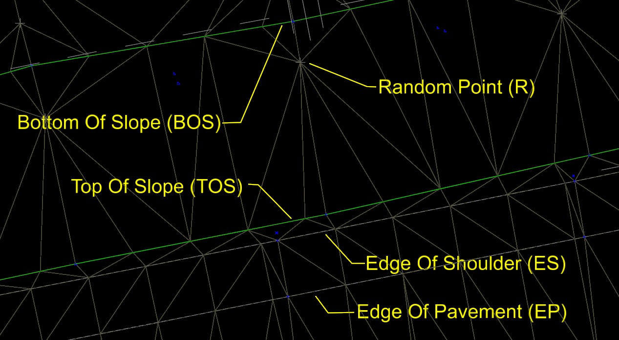
Figure 1: Break Line Features
Developing a terrain model that accurately represents real-world topography requires that surveyors assign the proper code to each terrain feature in the field (e.g., BOS, TOS). KYTC’s Data Collector Codes spreadsheet lists feature codes for linear and point features. In this spreadsheet, features with a “Yes” in the Triangulate column are used to develop a model of the existing terrain. Figure 2 shows a 3D rendering of a terrain model that utilizes break lines.
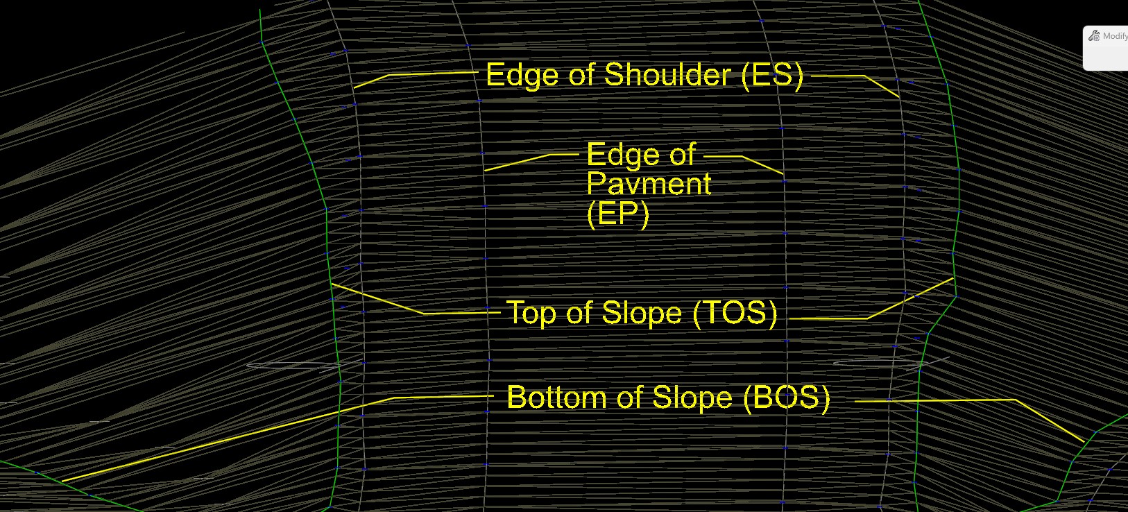
Figure 2: Wireframe Rendering of 3D Terrain
Planimetric Data
Planimetric data consists of 2D features that represent natural and constructed objects on the ground. These features are represented using predefined mapping symbols, and their positions are defined by x and y coordinates — elevation data (z coordinates) are not used. Planimetric features are not used to generate terrain models. Like terrain data, planimetric data consists of linear and point data.
In the Data Collector Codes spreadsheet, features that are only shown planimetrically have a “No” in the Triangulate column. In Figure 3, OHE, UFOCD and GYH are planimetric features and are not used in the terrain model.
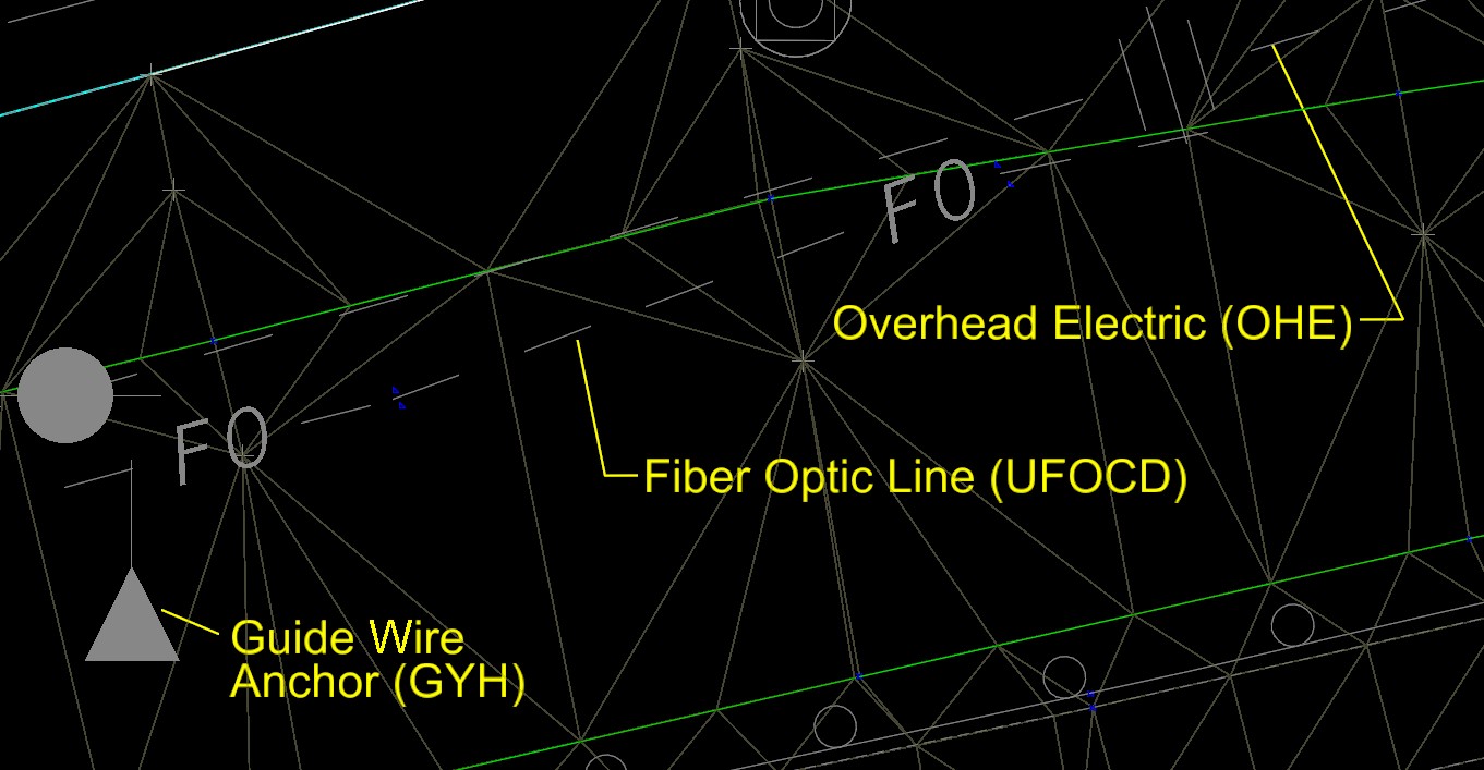
Figure 3: Examples of Planimetric Features
Side Note
3.1 Traditional Total Station and GNSS Receivers
Collecting project development survey data with total stations and GNSS receivers involves occupying every unknown point to determine its 3D position (x, y, and z coordinates). When using total stations, this is done through a survey process called traversing. When surveying is conducted with GNSS receivers, this is typically accomplished through real-time kinematic (RTK) methods. The HKP Article Surveying Equipment and Methods discusses total station and GNSS surveying.
When using either method, surveyors must understand the difference between break line and planimetric features in the field and code them correctly in the data collector.
3.2 Aerial Photography
Features captured via aerial photography are identified through photogrammetric post-processing techniques. These features are assigned feature codes as described in Section 3.1. Data collected via aerial photography must be tied to supplemental control. Supplemental control for aerial photography must be tied to primary or project control. See HD-302.5 Supplemental Control in the Highway Design Manual for more information.
See HD 308 Aerial Mapping in the Highway Design Manual and the HKP Article Surveying Equipment and Methods for more information on aerial photography and photogrammetry.
3.3 Light Detection and Ranging (LiDAR)
Like aerial photography data, lidar point clouds are post-processed to delineate terrain and point features. Features identified in point clouds are assigned feature codes as described in Section 3.1. Lidar data can be acquired by aerial and/or terrestrial (ground based) techniques and must be tied to supplemental control. Supplemental control for Lidar must be tied to primary or project control. See HD-302.5 Supplemental Control in the Highway Design Manual for more information.
For more information on lidar for highway design projects see the following references:
- HD-308 Aerial Mapping in the Highway Design Manual
- HD-309 Terrestrial Mapping Highway Design Manual
- HKP Article Surveying Equipment and Methods
Surveys of large streams must capture features that identify the shape of the streambed such as the thalweg, bank tops, and floodplain limits. Substantial portions of streams upstream and downstream drainage structures must be surveyed for hydraulic calculations. The surveyor should consult with the project designers to determine surveying needs for large streams in the vicinity of drainage structures.
The upstream and downstream inverts of small pipes and storm sewers must be surveyed. All pipe sizes should be noted in the survey.
Existing bridges and large culverts require a combination of surveying and field measurements to define their shapes. If a structure traverses a waterway, profile dimensions (viewed from direction of flow) are critical for determining the amount of flow that can pass through the structure. If a structure crosses a roadway, defining the bridge profile is critical for determining clearances. Enough information must be collected to define the shapes of headwalls and wing walls as well.
See HD 306.4 Drainage in the Highway Design Manual for more information on drainage surveys. See HD 303.7 Existing Structures in the Highway Design Manual and DR 805-5 in the Drainage Manual for more information on surveying structures.
Because utilities are located above and below ground level, special surveying techniques are required. All visible utility features on the ground surface should be surveyed, with their types and materials noted. Utilities are surveyed as planimetric features and not generally used to develop terrain models.
All poles that support overhead utilities must be surveyed. Capturing the elevations of low wires where overhead utilities are near proposed bridge structures or where they cross roadways is critical for the design process.
Establishing the locations of underground utilities requires the application of subsurface and surface engineering techniques. All marks on the ground that represent underground utilities must be surveyed. Different levels of subsurface utility engineering (SUE) are required for underground utilities. The Data Collector Codes spreadsheet has an extensive listing of codes used for display of utility planimetric data broken down by SUE level.
See the following references for more information on SUE:
- UR-304-5 Surveying in the Utilities & Rails Manual
- UR-803-1 Subsurface Utility Engineering (SUE) in the Utilities & Rails Manual
- HD-304 Utility Location in the Highway Design Manual
- HKP Article Subsurface Utility Engineering (SUE)
ROW surveys identify existing ROW and property lines. They are also used to set monuments for the proposed ROW. Surveys of existing ROW should capture both the ROW and property line monumentation. See HD-303.8 Property Line Features and HD-307 Right-of-Way Monumentation in the Highway Design Manual for information.
The Division of Highway Design administers two contracts that can be used to acquire survey data via private consultants:
Contact one of the survey coordinators listed on the Survey Coordination website for more information on the use of these contracts.
Deliverables for Project Development Surveys are discussed throughout HD-300 in the Highway Design Manual. The primary survey deliverables required include but are not limited to:
- MicroStation DGN file containing all graphics as described in HD-301.2 Standards
- Survey report as described in HD-301.6 Survey Reports
- Contract Documents as described in HD-301.7 Contract Documents
- Point files as described in HD-303.4 Data Collectors
- Terrian model of the existing surface as Described in HD-303.5 Digital Terrain Model (DTM)
There a several other deliverables required specific to the various data collection techniques described throughout HD-300.
KYTC Survey Manual (Chapter 300 of Highway Design Manual) (2026). Kentucky Transportation Cabinet.
KYTC Survey Self Help website.
Highway Knowledge Portal: Surveying Equipment and Methods
Highway Knowledge Portal: Subsurface Utility Engineering (SUE)