Search for articles or browse our knowledge portal by topic.
Roadside Safety in the Urban, Suburban, and Rural Town Contexts

Considerations for roadside safety in urban and suburban contexts differ significantly from those in a high-speed, rural context. Urban environments tend to be more confined, with a higher demand for functional use of the right of way. Traffic flow patterns and speeds vary due to the higher number of access points along urban roadways. Providing safe accommodations for non-motorized users of the roadside is a priority. This article explores roadside safety in urban, suburban, and rural town contexts.
Full definitions of the following terms mentioned in this article can be found in the HKP Glossary:
Rural – Areas with lowest density, few houses or structures (widely dispersed or no residential, commercial, and industrial uses), and usually large setbacks.
Rural town – Areas with low density but diverse land uses with commercial main street character, potential for on-street parking and sidewalks and small setbacks.
Suburban – Areas with medium density, mixed land uses within and among structures (including mixed-use town centers, commercial corridors, and residential areas), and varied setbacks.
Urban – Areas with high density, mixed land uses and prominent destination, potential for some on-street parking and sidewalks, and mixed setbacks
Urban Core – Areas with highest density, mixed land uses within and among predominately high-rise structures, and small setbacks.
Traveled Way – Portion of the roadway designated for the movement of vehicles (exclusive of shoulders).
Enhanced Lateral Offset – A wider-than-usual lateral distance between the edge of the traveled way and roadside hazards, particularly in urban areas where achieving full clear zone distances isn’t feasible.
Minimum Lateral Offset – The minimum lateral distance between the curb face – or from the outer edge of traveled way on roads without curbs – to the nearest edge of roadside objects (e.g., signing , lighting, utilities) allowing for normal operation of the roadway.
Border Area – In urban settings, the area between the face of curb and right-of-way line. It provides space in which to install roadside design components (e.g., signing, drainage features, sidewalks, and traffic control devices), establishes a buffer between vehicles and pedestrians, and may be used to accommodate permitted public utilities. It also provides space for constructing and maintaining the road.
Buffer Strip – Also known as the verge or utility strip, this area provides separation between sidewalks or shared-use paths (SUPs) and the vehicle traveled way. The appearance and texture should differ from the adjacent roadway and sidewalk or SUP.
Understanding the roadside safety needs in urban and suburban environments requires knowledge of how roadway contexts differ. Table 2-1 defines the five roadway contexts referenced in KYTC’s Highway Design Manual (HDM). For more information on Roadway Contexts, see the article Understanding Functional Classification and Context Classification.
| Table 2-1: Roadway Context Characteristics | ||
| Roadway Context | Features | |
| Rural |
|
|
| Rural Town |
|
|
| Suburban |
|
|
| Urban |
|
|
| Urban Core |
|
|
Recommended clear zone widths for high-speed roadways specified in Chapter 3 of AASHTO’s Roadside Design Guide (RDG) are often not practical or cost-effective in more urbanized contexts. For detailed information on urban roadside design, Chapter 10 of the RDG and Safe and Aesthetic Design of Urban Roadside Treatments (NCHRP Report 612) offer valuable guidance.
The following primary roadside design goals focus on safety and are applied across all contexts:
- Prevent vehicles from leaving the traveled way,
- Create a more forgiving roadside to reduce crash potential,
- Minimize the severity of impacts with fixed objects.
In more urbanized contexts, the likelihood of non-motorized occupying roadsides increases. Beyond addressing motorist safety, it is important to prioritize the safety of pedestrians and cyclists who use roadside spaces.
In non-rural areas with higher speeds and a low number of access points, a best practice is to use clear zone distances recommended in Chapter 3 of AAHSTO’s Roadside Design Guide (RDG).
In urban areas where it is not feasible to apply RDG clear zone distances for high-speed roadways, rigid objects should still be located as far away from the active traveled way as practical. Identifying critical roadside locations in urban areas is essential for prioritizing roadside safety improvements. Table 3-1 lists recommended enhanced lateral offset values that can be used in lieu of RDG clear zone values.
| Table 3-1: Enhanced Lateral Offset Values for Urban Roadways | ||||
| Location | With Vertical Curb¹ | Without Vertical Curb² | ||
| Outside-of-Curve | 6 ft. | 12 ft. | ||
| Other Locations (not outside of curve) | 4 ft. | 8 ft. | ||
|
||||
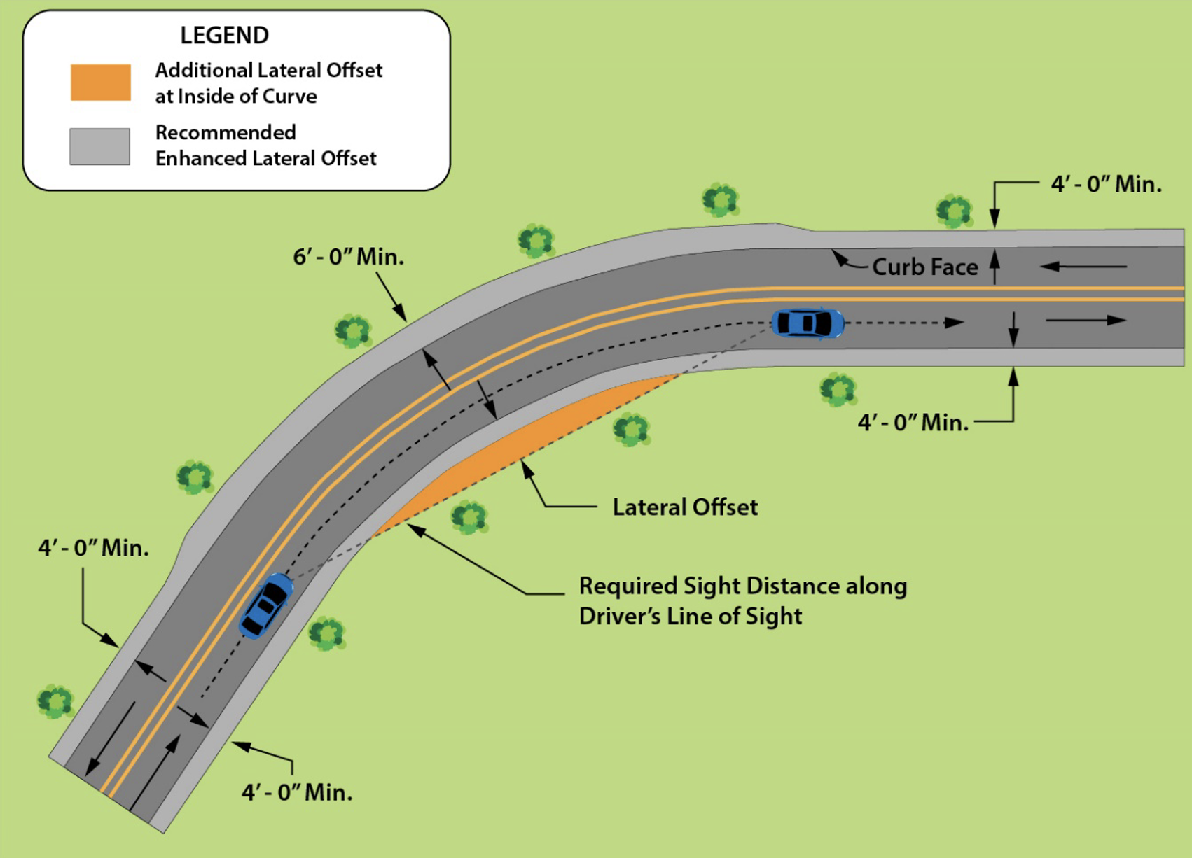
Figure 3-1: Enhanced Lateral Offset
The HKP article Enhanced Lateral Offsets in Urban Environments provides more information.
Enhanced lateral offsets in central business districts (CBDs) with on-street parking (i.e., urban core contexts) or on low-speed local roads may not be practical.
3.1. Minimum Lateral Offset
The purpose of a minimum lateral offset differs from that of an enhanced lateral offset. It is the minimum lateral distance between the curb face and where the edge of objects can be placed. Typically, it is 1.5 ft. Minimum lateral offset for roads without curbs is generally 4 ft. This offset was established to prevent truck mirrors and other vehicle extensions from hitting rigid objects. In constrained urban areas where it is not feasible to provide enhanced lateral offsets, this should be the minimum lateral offset provided. Recommended minimum lateral offsets for intersections are discussed in the next section.
While most intersection crashes involve vehicle-to-vehicle collisions, crashes with roadside objects do occur. To address roadside safety at intersections, consider the following:
- If channelization islands are present or planned, construct them according to guidelines in AASHTO’s Green Book. Ensure the design vehicle can be accommodated. Do not place rigid objects at the corner island or the median nose.
- Enhanced lateral offset at intersections reduces the likelihood of roadside collisions with fixed objects and improves intersection sight distance. The recommended lateral offset at intersections with curbed facilities is 6 ft. The minimum is 3 ft. Facilities without curbs should have rigid objects placed as far as possible from the lane edge.
- Consider placing pedestrian buttons for crosswalks on breakaway pedestal poles adjacent to the directional ramp rather than a rigid traffic signal pole. This allows the pole to be placed further from the intersection.
- Follow Public Right-of-Way Accessibility Guidelines (PROWAG) requirements for curb ramps.
5.1. Curbs
Except for vehicle impacts at very low operating speeds (≤ 25 mph), curbs typically have no redirectional qualities. That is, they will not redirect an errant vehicle. When a curb is adjacent to the traveled way, the minimum operational clearance must be 1.5 feet. For roadways with design speeds ranging between 30-45 mph that have a curb adjacent to the traveled way, the border area (see Section 5.4) should be free of obstacles. Curbs in low-speed, urban areas are typically 6 in. vertical curbs. See KYTC’s Standard Drawing RPM-100 for curb design details.
For suburban areas or transition zones that link higher-speed to lower-speed facilities, consider providing a shoulder and offsetting the curb to the back of the shoulder. An offset ≥ 8 ft. is recommended. Roadways with design or posted speeds > 45 mph should not include curbs. However, if curbs are used, they should be mountable, no higher than 4 in., and placed at the outside edge of the shoulder.
5.2. Shoulders
If shoulders are present, they are part of the clear zone width. Shoulder widths on urban and suburban facilities are not prescribed. Wider shoulders reduce the risk of roadway departures but may also increase travel speeds.
5.3. Medians
Raised medians are considered part of the roadside. Apply lateral offsets discussed in Section 3. Only crashworthy objects should be placed in a median. If rigid objects are present, they should be shielded. See the HKP article Median Barrier Application (coming soon). Wider medians reduce the risk of roadway departure crashes.
5.4. Boarder Area
The border area encompasses the roadside of an urban facility, extending from the face of the curb to the right-of-way line. This space should be wide enough to accommodate multiple functions, such as providing a buffer between pedestrians and vehicles, supporting pedestrian or shared-use facilities, and allowing space for utilities. Typical dimensions for border areas are shown in HDM Exhibit 700-06. However, the actual widths and slopes may vary based on factors like roadway context (refer to HDM Exhibit 700-04 for minimum widths), available right of way, terrain, the presence of multimodal facilities, and other considerations. Figure 5-1 is from HDM 700 Exhibits.
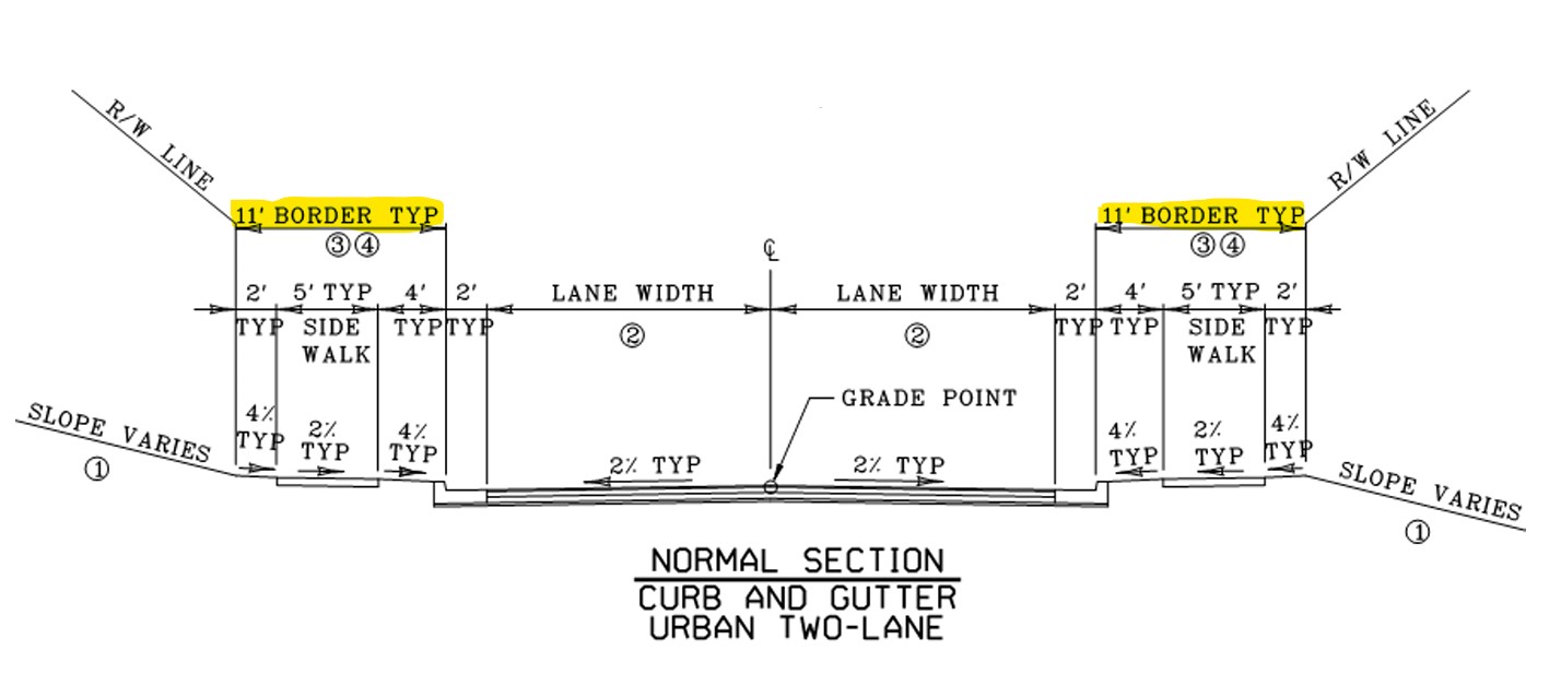
Figure 5-1: Typical Section of an Urban Two-Lane Roadway (from HDM Exhibit 700-06)
5.4.1. Roadside Grading
On curbed roadways, the adjacent roadside usually slopes towards the curb to convey roadside drainage into a closed drainage system. See HDM Exhibit 700-06 for typical slopes. Consider slopes that can accommodate the inclusion of bicycle or pedestrian facilities. Slopes without curbs should follow the guidance for rural roadside in Chapter 3 of the RDG or the HKP article Clear Zone Overview.
5.4.2. Buffer Strip
The buffer strip, sometimes referred to as the verge or utility strip, separates sidewalks or shared-use-paths (SUPs) from the vehicle traveled way. On curbed facilities with driveways, they provide room to install a sloped driveway without impacting the slope of the shared-use path. The buffer strip can be vegetated with low-to-the-ground grass or shrubs, or it can be paved. The appearance and texture of paved buffer strips behind the curbs should differ from the adjacent roadway and sidewalk or SUP. A buffer strip is typically 4 ft. wide (minimum 2 ft.) where sidewalks are present and should be at least 5 ft. wide when SUPs are included in the border area. When non-breakaway features are present in the buffer strip, place them as far from the curb as practical. If the buffer strip is less than 4 ft., place rigid objects at the far side of the sidewalk.
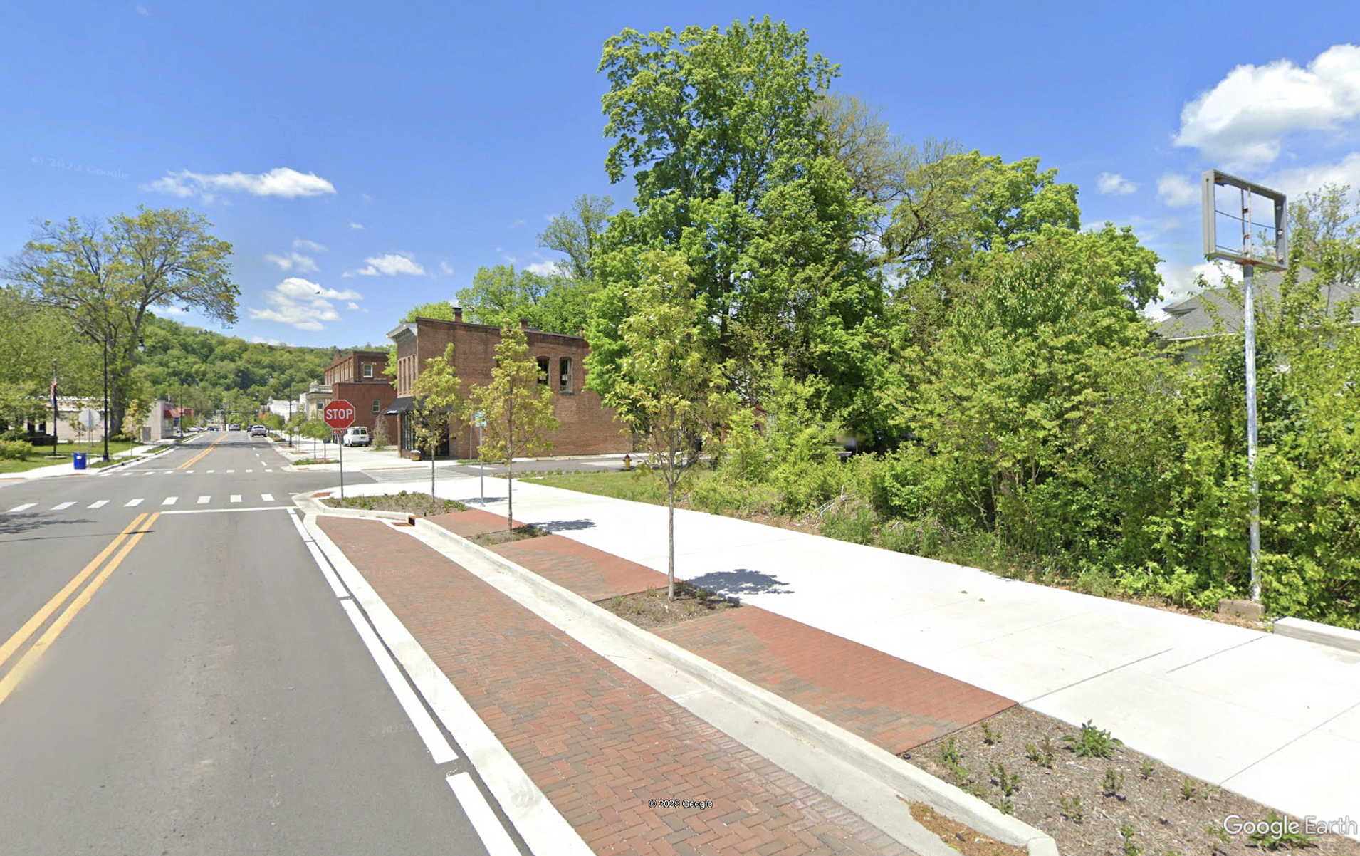
Figure 5-2: Paved Buffer Strip (Source: Google Earth)
In urban areas with limited right-of-way, sidewalks may need to be placed next to the curb. In such cases, a sidewalk width of at least 6 ft. is recommended. In areas with higher speeds and traffic volumes, consider installing a physical barrier for added protection.
5.4.3. Guardrail
The use of guardrail within the border area should be carefully evaluated. If guardrail is utilized in a border area, it should present less of a hazard than the obstacle being shielded. For information on the lateral placement of guardrail, see Section 3 of the HKP article Guardrail.
5.4.4. Sidewalks and Shared-Use-Paths
Consider pedestrian and bicyclist safety when locating sidewalks and SUPs within the border area of a roadway. AASHTO’s Guide for the Planning, Design, and Operation of Pedestrian Facilities, PROWAG, and AASHTO’s Guide for the Development of Bicycle Facilities should be consulted for the design of these facilities. HD-1500 and KYTC’s Complete Streets Roads and Highways Manual also provides guidance.
5.5. Parking
Restrict on-street parking to low-speed roadways. Parallel or back-in angle parking is preferred. According to HDM Exhibits (700 series), parking lanes should be 7-8 ft. wide in residential areas and 8-11 ft. wide in commercial and industrial areas. Install buffers between parking lanes and through traffic if possible.
5.6. Roadside Treatments and Hardware
Ideally, a roadside should be clear of all obstructions as this will improve roadside safety. However, this is often not possible because roadsides are shared spaces that accommodate a number of uses.
5.6.1. Mailboxes
Mailboxes must be located close to the roadway so they can be accessed by mail delivery vehicles. On urban roadways, they may be located in the buffer strip. On higher speed facilities without curbs, such as transitions zones, suburban areas, or rural town contexts, mailbox turnouts may be used to move the mailbox further away from the road. KYTC’s Standard Drawing RPM 110 provides guidance on mailbox turnouts. Crashworthy mailbox designs are preferred. Mailboxes installed on Department right-of-way must meet Maintenance policy MAIN-611. The mailbox face is typically 6-8 in. behind the curb or edge of roadway surface.
5.6.2. Utilities
KYTC’s Utility and Rails Guidance Manual (UR-401-2) addresses clear zone requirements for utility accommodations (e.g., poles, hydrants, regulators, junctions, cabinets, stations, and other structures). See Sections 3 and 4 for additional details.
5.6.3. Roadside Traffic Treatments and Hardware
KYTC’s Traffic Operations (TO) Guidance Manual includes guidance on the roadside location of vertical traffic appurtenances (e.g., light and signal poles, signs). Typically, all rigid traffic appurtenances with non-breakaway supports should be placed outside the clear zone. In low-speed, urban areas place them outside the enhanced lateral offset (see Sections 3 and 4). Lighting poles with non-breakaway supports may be used in low-speed (≤35 mph) urban environments with significant pedestrian activity, if justified through an engineering study (TO-705). See TO-710 for guidance on intersection lighting luminaire location.
5.6.4. Street Furniture
In urban areas, place street furniture (e.g., tables, benches, trash cans, planters, bollards, transit shelters) as far as possible from the roadway in a manner that does not create sight distance issues for roadway users.
5.6.5. Roadside Barriers
Place roadside barriers as far from the traveled way as practical. In urbanized areas, greater consideration should be given to protecting pedestrians, other non-motorized users, and adjoining properties.
6.KYTC Reference Documentation
- Complete Streets, Roads, and Highways Manual
- Highway Design Manual
- Exhibit 700-04
- Exhibit 700-06
- HD 702.10.4 Curb Placement and Border Area
- HD 702.10.6 Medians
- HD 7-3.5 Context Classification
- HD 800 Roadside Design
- HD 1500 Pedestrian & Bicycle Accommodations
- Maintenance Guidance Manual
- MAIN 611 Maintenance of Mail Boxes Prohibited
- Permits Guidance Manual
- PE-1701 Transit Shelters
- Standard Drawings
- Traffic Operations Guidance Manual
- TO-705 Plan Development
- TO-710 Intersection Delineation Lighting
- Utility and Rails Guidance Manual
- UR 401-2 Design Considerations
7. References
AASHTO (2018) A Policy on Geometric Design of Highways and Streets. 7th Edition, The American Association of State Highway and Transportation Officials, Washington DC.
AASHTO (2024) Guide for the Development of Bicycle Facilities (5th ed.). The American Association of State Highway and Transportation Officials, Washington, DC.
AASHTO (2021) Guide for the Planning, Design, and Operation of Pedestrian Facilities (2nd ed. ). The American Association of State Highway and Transportation Officials, Washington, DC.
AASHTO (2011) Roadside Design Guide. Fourth Edition, RSDG-4, The American Association of State Highway and Transportation Officials, Washington, DC.
Dumbaugh, E. (2006). Design of Safe Urban Roadsides: An Empirical Analysis. Transportation Research Record, 1961(1), 74-82. https://doi.org/10.1177/0361198106196100109
National Academies of Sciences, Engineering, and Medicine (2008) Safe and Aesthetic Design of Urban Roadside Treatments. NCHRP Report 612, Washington, DC: The National Academies Press. https://doi.org/10.17226/14171 .
U.S. Access Board. Public Rights-of-Way Accessibility Guidelines (PROWAG). U.S. Access Board, www.access-board.gov/guidelines-and-standards/streets-sidewalks/prowag/ .
