Search for articles or browse our knowledge portal by topic.
Subsurface Investigation Tools and Techniques
When most people envision subsurface investigations, they think of drill rigs, soil samples, and rock cores. While those items are a major part of KYTC’s subsurface investigations, other tools and techniques are available to investigate and understand subsurface conditions at a project site. Application of these tools is valuable during project design as well as when construction or maintenance problems arise. This article introduces some of the most common tools and methods used during subsurface investigations.
To learn more about initiating a geotechnical investigation, refer to the Highway Knowledge Portal article Geotechnical Investigations – Where to Begin and How to Proceed.
A conventional subsurface investigation program involves drilling and recovering samples of soil and rock materials (Figure 1). Geoprofessionals analyze materials to determine:
- Stratigraphy
- Depth to bedrock
- Depth to groundwater
- Properties needed for design
KYTC’s Geotechnical Manual provides more information on conventional drilling and sampling methods.
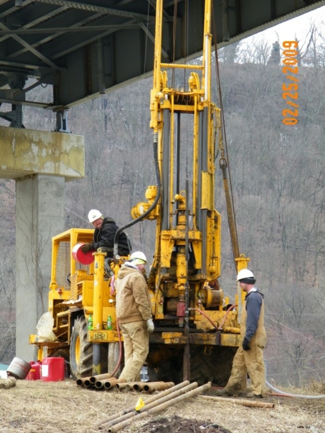
Figure 1. KYTC drill crew using an all-terrain rig at the Milton-Madison Bridge in Trimble County
2.1 Drill Rigs
Several types of drill rigs are used for rotary drilling. They are often adapted for specific applications and terrain. Table 1 lists the typical types of drill rigs.
| Table 1. Drill Rig Types | |
|---|---|
| Drill Rig Type | Terrain Type and Application |
| Truck-Mounted | Sites that can be accessed easily or without extensive site preparation |
| All-Terrain | Sites with difficult terrain or soft ground |
| Track-Mounted |
Sites with heavily wooded terrain, steep terrain, or swampy soft ground 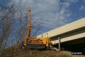 |
| Skid-Mounted | Sites with steep terrain |
| Jack-Up Barge Mounted |
Drilling over water 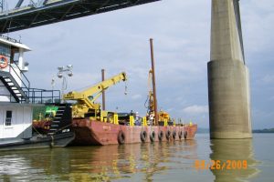 |
2.2 Auger Borings
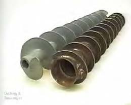
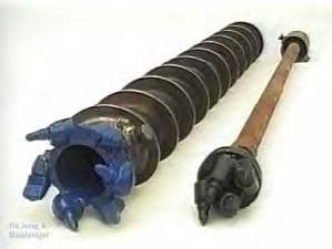
The method of drilling and obtaining samples KYTC relies on most often is rotary drilling using augers (Figure 2). Solid stem augers are typically used to advance borings into soil to identify the top of bedrock (rockline soundings) or obtain disturbed samples of soil for pavement subgrade and earthwork design.
Hollow stem augers are used when samples of soil or rock need to be retrieved and tested for the design of foundations, embankments, and cuts. The auger is advanced to the sampling depth with a plug placed in the hollow portion of the auger. This plug prevents material from coming up inside the auger. The plug is then removed, and a sampling tool is inserted into the auger.
The auger serves as a casing to prevent the drill hole from collapsing as well as to keep cuttings or other materials from falling back into the hole and contaminating the sample.
Hand augers can be used to obtain samples in difficult-to-reach locations or where the depth of investigation is shallow. Samples obtained through this method are small, and they are used for soil index and classification tests if enough material can be retrieved.
2.3 Wash Borings
A less common method of advancing borings is wash-type borings. Wet rotary or wash borings are commonly uncased, and drilling fluid is injected to remove cuttings from the borehole as well as to stabilize boring sidewalls against collapse. The drilling fluid may be pure water or it may consist of water mixed with bentonite or polymers to create drilling mud. Using drilling mud helps maintain stability of the borehole sidewalls. If drilling fluid cannot stabilize the sidewalls, a casing can be used.
Wash borings are useful when non-cohesive soils are present. In non-cohesive soils (e.g., sands, some silts), soil particles do not stick together. These kinds of soils may liquify or collapse if there are differences between the fluid level in the borehole and groundwater. This commonly occurs in and around bodies of water (e.g., lakes, rivers, and overbank areas). If soil liquifies, the borehole’s sidewalls collapse. If casings are used, soil that liquifies may flow up from the bottom of the boring into the casing a considerable distance. In either situation it is not possible to obtain a representative sample of the soil material. Thus, maintaining the drilling fluid level in the borehole above the surrounding groundwater or lake level is important to keep the boring stabilized.
2.4 Soil Sampling
2.4.1 Shelby Tube
Shelby tube sampling is used to obtain relatively undisturbed soil samples to measure strength, permeability, consolidation, and other properties. To obtain a sample whose characteristics represent those of the in-place soil, sampling is done in a manner that minimizes disturbance to the soil.
To obtain a sample, a standardized tube is pushed into the ground and then removed. The sample is then extracted from the tube, visually logged, and tested immediately or preserved for later testing. This method works well for clayey or silty soils that have some cohesion and do not fall apart when extracted from the tube. It is not suitable for sampling non-cohesive soils.
2.4.2 Standard Penetration Test (SPT)
The SPT involves driving a sampler into the ground using a 140-pound hammer dropped from a height of 30 inches. The sampler is driven three consecutive 6-inch intervals, and the number of blows required to drive each of the 6-inch intervals is recorded. The sampler is then retrieved and opened to obtain a soil sample. The number of blows can be related to soil properties such as strength and density.
SPT samples are suitable for typical soil index and classification testing. Since these samples are considered disturbed, they are not suitable for strength, permeability, consolidation, and other types of testing where undisturbed samples are required. SPT sampling is suitable for non-cohesive soils. It can be used in clayey or silty materials that are cohesive, but use of the blow counts to determine soil strength is not considered particularly reliable for cohesive materials and should be used with caution.
2.4.3 Bag Samples
Bag samples are gathered from auger cuttings and are obtained when bulk samples of soil material are needed for classification, density, resilient modulus, and California Bearing Ratio (CBR) tests. Bag samples are often collected to gather information related to pavement subgrade strength, but they can be acquired for other purposes such as evaluating the suitability of borrow pits or to identify materials used for embankment construction. When a bag sample is gathered, a small portion of the material is sealed in a jar to quantify the soil’s natural moisture content.
2.4.4 Test Pits
Test pits can be excavated and used to help characterize subsurface conditions. They are particularly valuable when excavation is required only to a relatively shallow depth. Test pits can be excavated by hand or by power equipment, and soil samples can be retrieved for testing.
2.5 Rock Sampling
2.5.1 Rock Coring
Rock coring is conducted using a core barrel with a cutting bit. The cutting bit is often diamond impregnated, and fluids such as water are used to flush cuttings to the surface. Core barrels have inner and outer tubes to help capture and protect cores from being damaged during the coring process. Barrels are retrieved from bore holes and opened to access cores. Once retrieved, a core is placed in a core box for transport and storage (Figure 3).
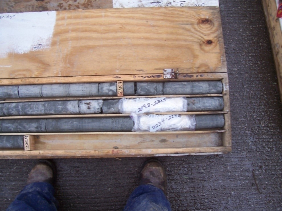
Figure 3. Rock core placed in core box with two wrapped samples for strength testing
Geologists evaluate cores to determine the rock type; identify fractures, joints, dips, voids; and assess durability against weathering (Slake Durability Index or SDI). For some types of foundations, strength testing must be done on core samples. Once testing is finished, cores are placed into storage until construction is completed. However, they may be stored permanently if the structure is of particular importance. Contractors often wish to view cores when preparing their bids as rock excavation can be a major component of roadway or structure foundation construction.
2.5.2 Open-Face Logging of Rock Cuts
When rock outcrops are visible or when rock cuts already exist on a project, open-face logging of the outcrops or cuts can be performed in lieu of or as a supplement to rock coring (Figure 4). The outcrop or rock cut exposes the lithology, dip, fractures, and joints of bedrock more completely than a rock core would. Samples of exposed rock can also be obtained for SDI testing.
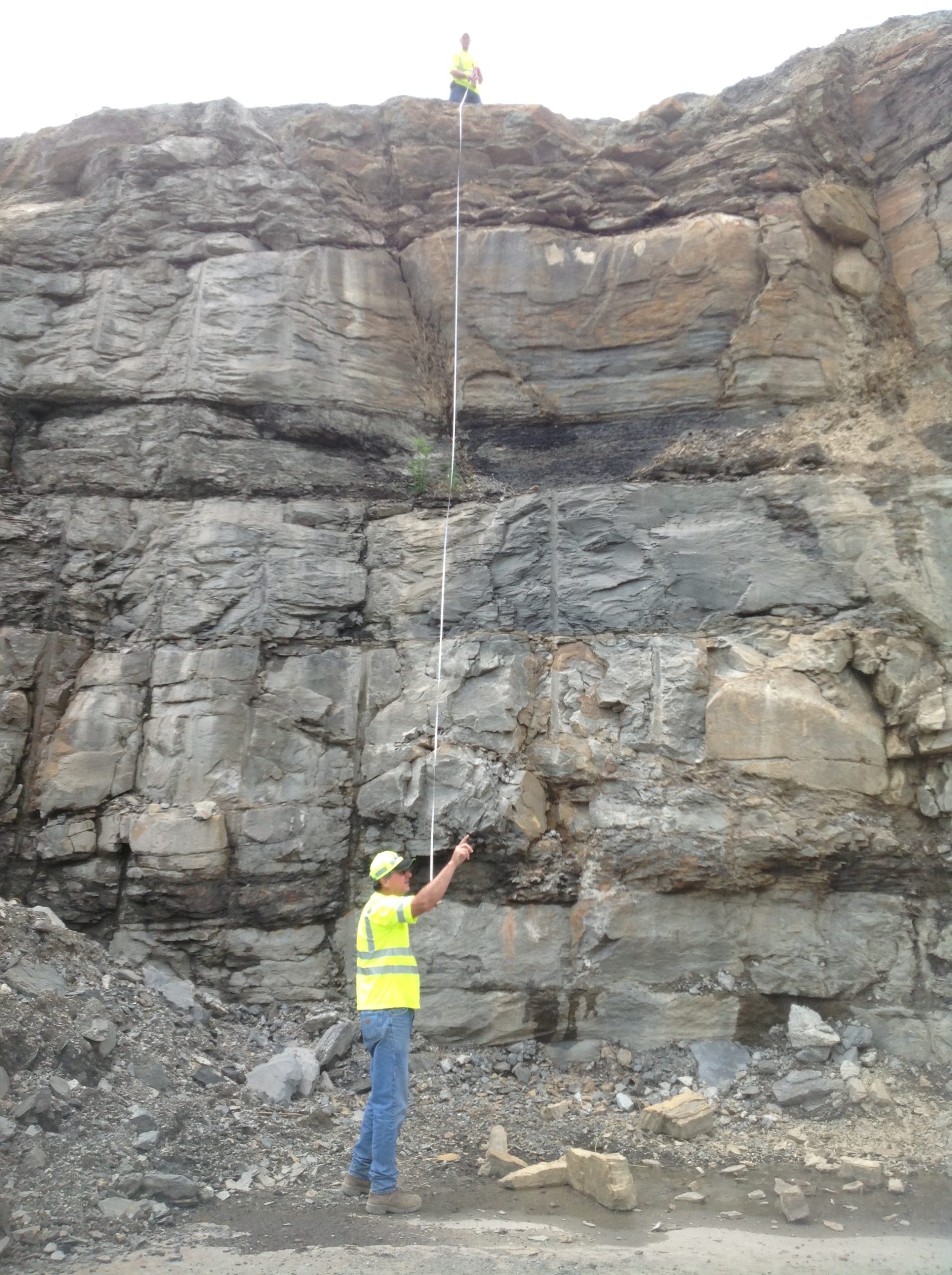
Figure 4. Open Face Logging of a Rock Cut Slope
Although most subsurface investigations conducted by KYTC and its consultants rely on conventional methods, other methods are available that are becoming more common.
3.1 Cone Penetrometer
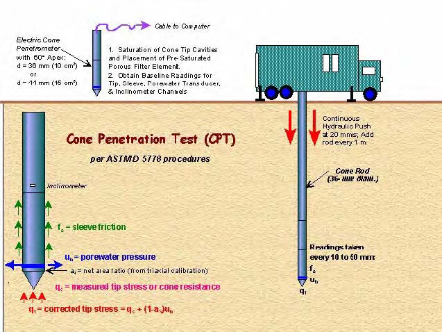
Cone penetration testing (CPT) involves pushing an instrumented probe into the ground at a constant rate (Figure 5). Instrumentation measures the stresses on the tip and sleeve of the probe. This test produces no borehole, cuttings, or spoil; however, it does not allow direct sampling of the material being tested. CPT is fast and economical, but it requires experienced operators. It is particularly suited for soft soils but can be used in some dense sand deposits. Because the test provides a continuous log of the soil response as the probe is pushed through the soil, it detects thin soil layers that could be missed with conventional soil sampling. A number of methods are available to analyze and interpret CPT data. These data can also be correlated with other soil parameters to understand the soil characteristics. Since soil samples are not obtained with this method, it is often combined with conventional borings.
Cones often have instrumentation embedded to measure other parameters. Piezo elements are often included in a cone to measure soil pore water pressures during the test. Geophones can also be included in the cone to measure shear waves passing through the subsurface, and this provides valuable data to help design projects located in seismic zones.
3.2 Electrical Resistivity
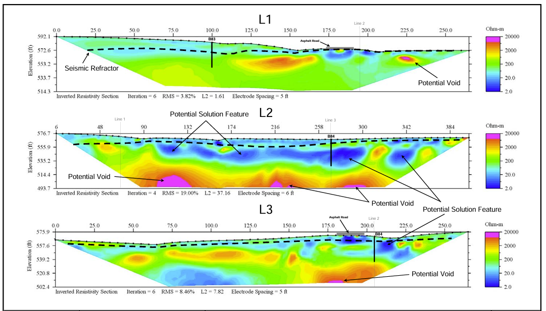
Subsurface electrical resistivity is measured by applying DC current to the ground with an electrode. Additional electrodes are placed along a line where voltage measurements are made. This method is commonly used to identify underground anomalies such as karst features, caves, voids, buried tanks or waste, and groundwater as well as soil depths (Figure 6). The resolution of electrical resistivity data decreases with depth. Experience is needed to interpret graphical outputs.
3.3 Borehole Camera
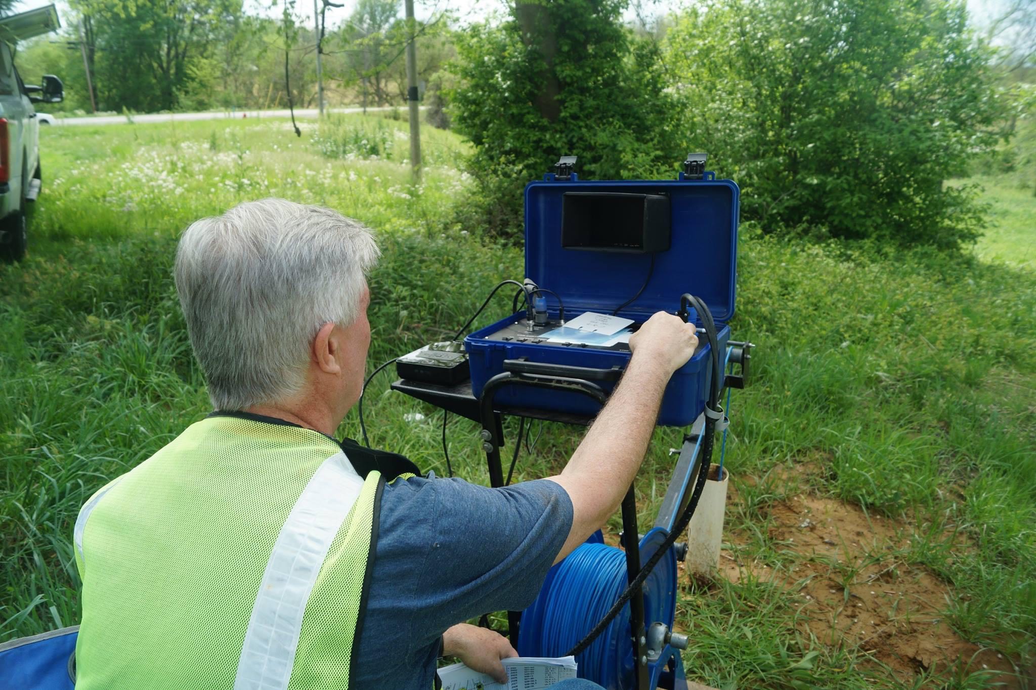
Borehole camera systems — also known as water well inspection cameras — can be used to inspect boreholes and underground features boreholes encounter. This type of inspection can be useful in areas where caves, mines, or other voids may be present underground. In other cases, it may be useful for viewing materials that the borehole penetrates to identify fractures, joints, or other defects. Video recording equipment can be added to provide a record of the viewing (Figure 7). The linked video is a recent use of the borehole camera to investigate an abandoned mine beneath a proposed bridge project (mine is encountered at about 10:00 minutes into the video at a depth of 90.4 feet). Videos were provided to contractors to aid in the bidding process.
3.4 Borehole Laser Scanner
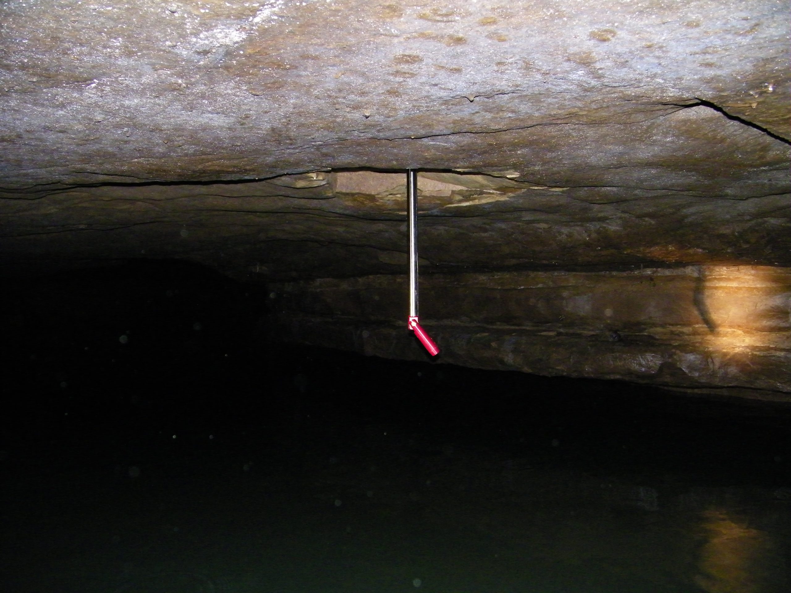
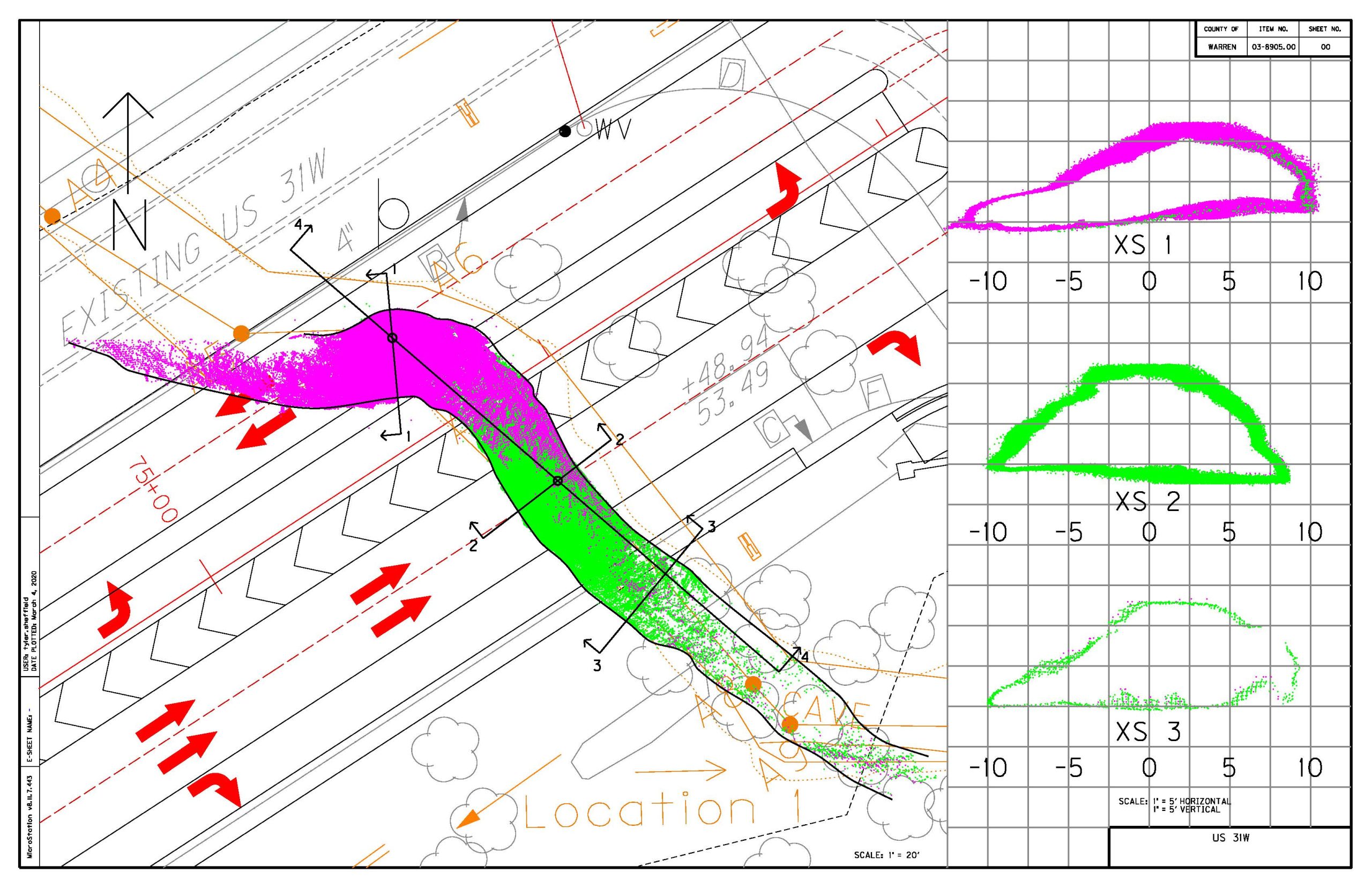
Borehole laser scanners are used to map underground areas such as caves, tunnels, and mine works (Figure 8). Compared to traditional surveying methods, their use facilitates underground surveys that are efficient, safer, and more accurate. Point clouds generated from the laser scan can be used along with other data collected for a project to map critical geological features (Figure 9). A drawback to borehole laser scanners is that they cannot be used underwater. Scans also reflect off standing water, so accurate representation of the size of a void or cave that contains standing water requires that laser scans be supplemented with other measurement methods.
3.5 Other Techniques and Tests
3.5.1 Seismic
Seismic test methods provide data on shear wave velocities, soil stiffness, and depth to bedrock. They are done by first placing sensors on the ground, typically in a linear fashion. An impact is then applied to the ground at one end of the line of sensors, and the sensors measure the time it takes for the shear wave from the impact to arrive. Seismic tests can be particularly useful when evaluating the effects of earthquakes on projects. Significant expertise is required to interpret test results.
3.5.2 Ground Penetrating Radar (GPR)
GPR can be used to determine depth to the water table, identify buried objects, measure the thicknesses of pavement layers, and detect voids (Figure 10). It is not effective below the water table or in clayey soils, and depth of penetration is limited.
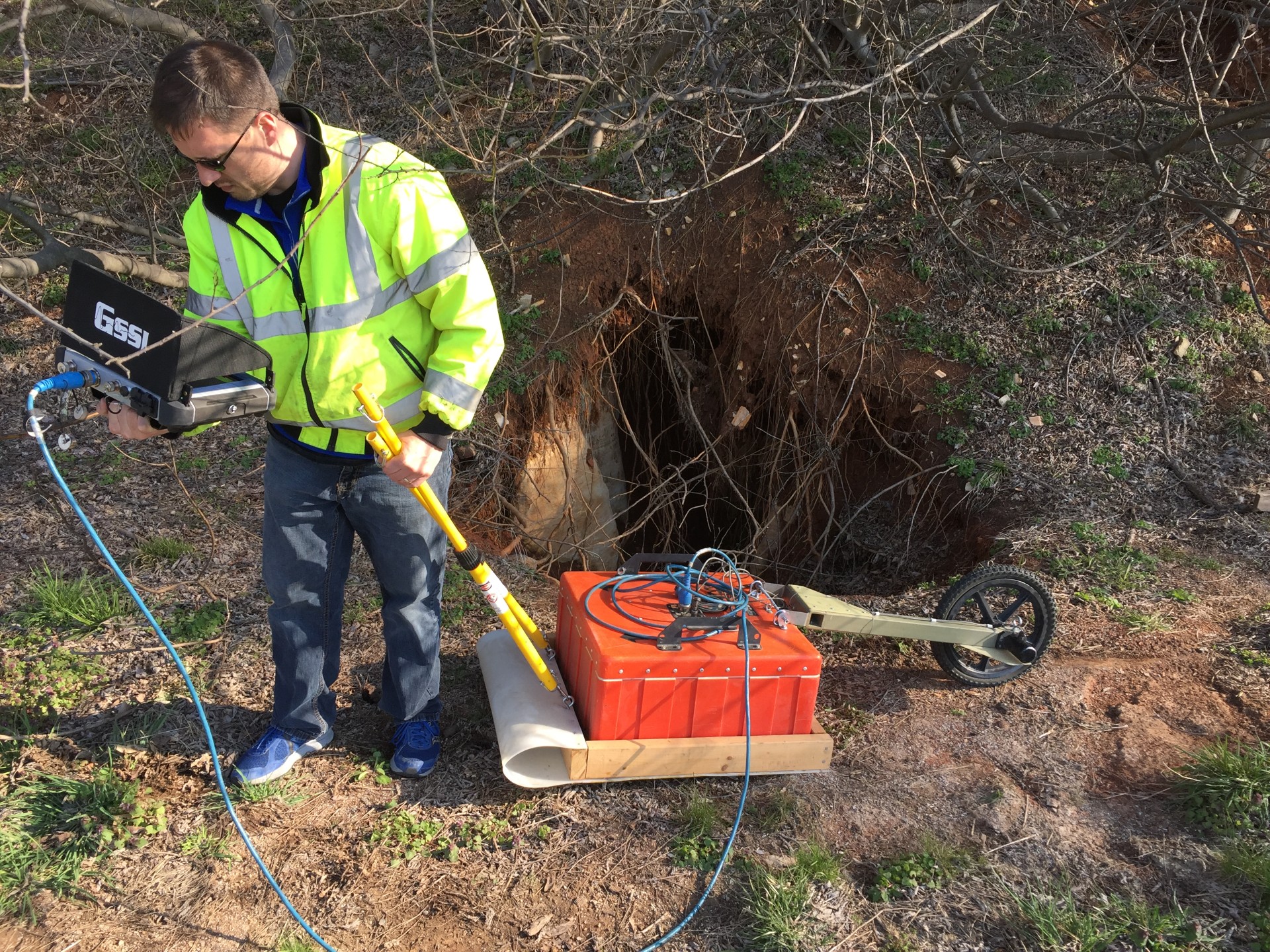
Figure 10. Ground Penetrating Radar testing using a 200 MHz deep antenna
3.5.3 Field Devices for Measuring Soil Strength
Many devices are available to measure soil strength and related parameters in the field or without standard laboratory equipment. Common methods utilized by KYTC are described below.
3.5.3.1 Vane Shear
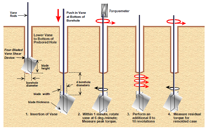
Vane shear tests are used to measure the undrained shear strength of soil in-situ. They are particularly valuable for evaluating soft to medium clays where retrieving an undisturbed sample may be difficult. The test is conducted by pushing a four-bladed vane into the soil at the bottom of a boring (Figure 11). The vane is slowly rotated while measuring the torque until the soil shears. Torque measurements are used to determine the undrained soil’s shear strength
3.5.3.2 Dynamic Cone Penetrometer (DCP) Test
The DCP test measures an in-situ soil’s resistance to penetration. It is conducted by driving a metal cone into the ground by repeatedly dropping an 8 kg weight onto the cone from a height of 575 mm. Resistance values measured from DCP tests can be correlated to other measures such as the soil’s density, resilient modulus, CBR, and bearing capacity. The DCP test can be used during construction for quality control and assurance purposes, but it can also be used to obtain design information in areas where accessing a site with conventional testing or drilling equipment is difficult.
3.5.3.3 Pocket Penetrometer and Torvane
Pocket penetrometers and torvanes are handheld soil testing devices used to measure soil strength. To measure compressive strength with a pocket penetrometer (Figure 12), the user pushes a piston into soil a given distance and measures the force required to achieve that penetration. Torvanes (Figure 13) measure soil strength using a method similar to vane shear tests — vanes are inserted into soil and rotated until failure while measuring the torque required to achieve failure.
While these devices are convenient for field use to help determine the strength of cohesive fine-grained soils (clays and some silts), they can also be used in more traditional laboratory settings to supplement data from traditional tests. They are not suitable for determining strength of non-cohesive soils (sands and some silts). Care must be taken when using the results of pocket penetrometer and torvane tests as the tests represent very small samples of soil, and the results can vary greatly.
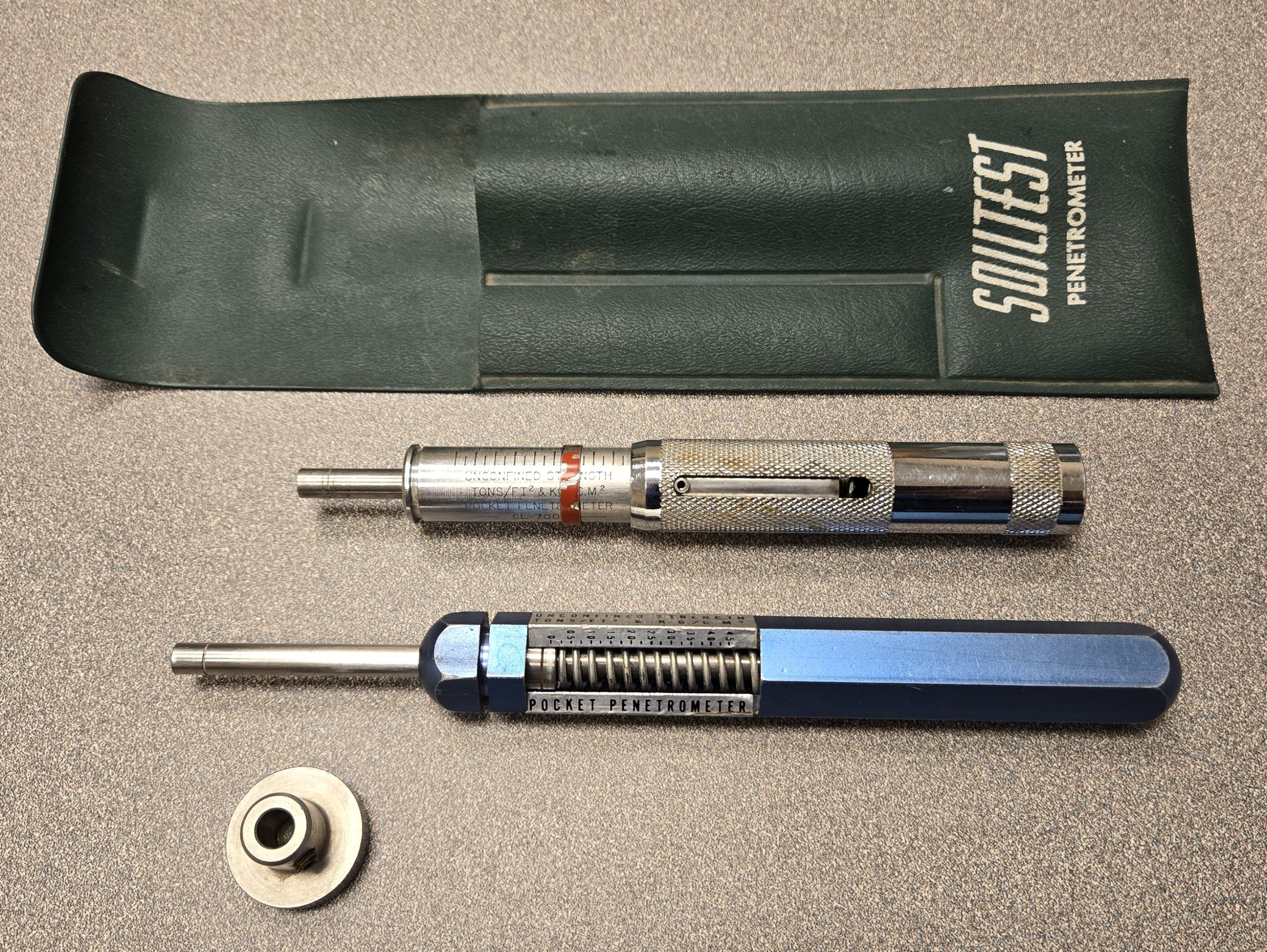
Figure 12. Pocket Penetrometers with adapter foot for soft soils
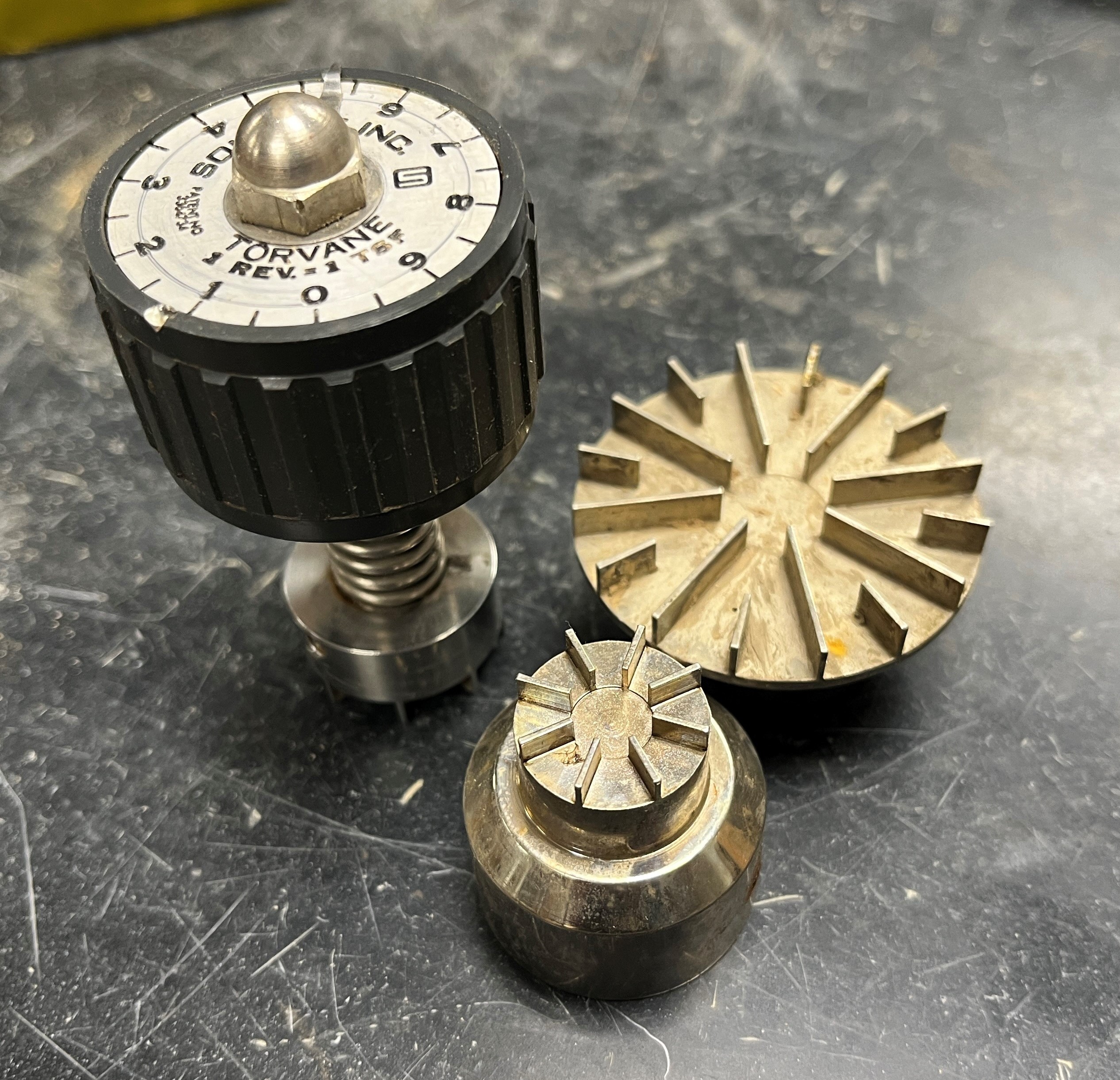
Figure 13. Torvane with adapters for stiffer (smaller adapter) and softer (larger adapter) soils
4.1 Observation Wells
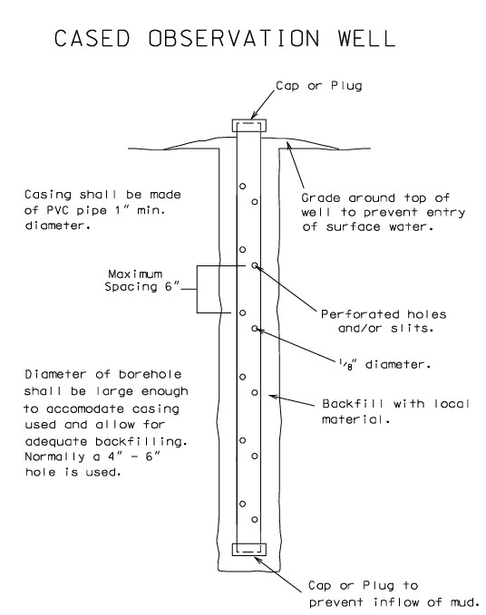
Observation wells are used to measure groundwater levels. The presence of groundwater or excess water pressures in soil reduces available soil strength, thus knowing the water level and pore pressures is an important factor in geotechnical engineering. Wells usually consist of PVC pipe with slots or holes that are installed in a borehole (Figure 14). After allowing the groundwater level to stabilize in the well (usually about one week), depth to groundwater is measured. Since groundwater levels fluctuate seasonally and in response to precipitation, additional readings can be taken to document changes in groundwater levels over time.
4.2 Piezometers
Like observation wells, piezometers are used to measure underground water pressures. A piezometer is installed in a borehole at a specified depth. Cables or tubing are run from the instrument to a location outside of the construction zone so the piezometer can be read without interfering with construction. Piezometers are often installed for embankment construction on soft or saturated soils where excess pore water pressures from construction could cause the embankment to fail. When embankment failures are possible due to excess pore water pressures, controlled or staged construction of an embankment is usually specified. Piezometer readings inform the rate at which embankment construction occurs so that failure is avoided. Piezometers are often installed in conjunction with settlement plates or sensors.
4.3 Settlement Plates and Sensors
Settlement plates and sensors are used to measure settlement due to embankment or foundation loads. They are often installed in conjunction with piezometers. Settlement plates consist of a flat steel plate installed under an embankment. An attached steel pipe extends to the surface so that survey readings can be made (KYTC Standard Drawing RGX01503) (To view standard drawing, click on the link. Type in drawing # into table. Do not include any dashes or spaces).
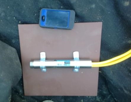
Settlement sensors (Figure 15) are installed in boreholes or on the ground surface and use fluid pressure to measure elevation changes over time and thus the settlement of the sensor.
Settlement plates and/or sensors are commonly installed at bridge abutments or other structure locations where settlement may stress or damage a structure.
4.4 Slope Inclinometers
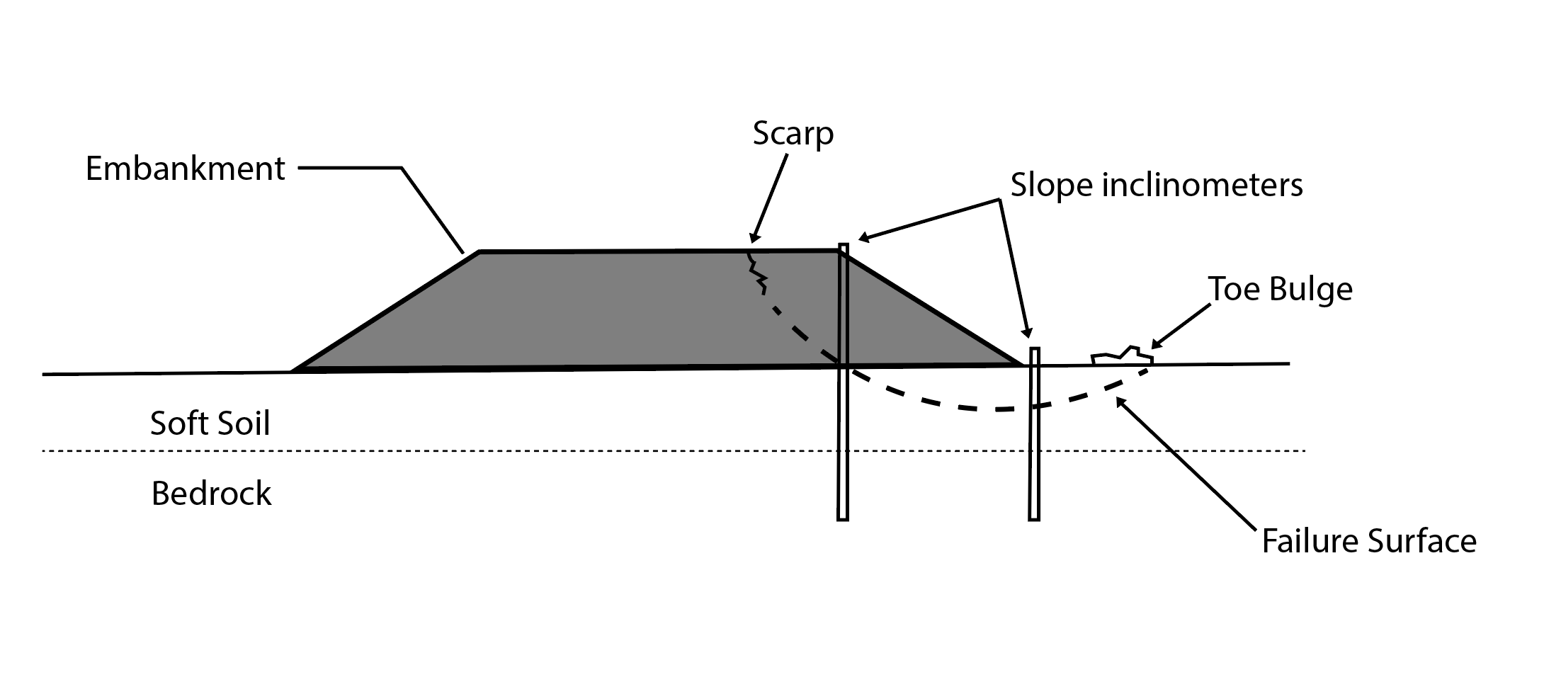
Slope inclinometers are used to monitor subsurface movement such as unstable slopes and embankments (Figure 16). First, a special casing that accommodates a slope inclinometer probe is inserted into a borehole. The probe is then lowered to the bottom of the casing and raised at specified intervals. The probe’s tilt is measured at each interval. When data are processed they show the casing’s shape. When readings are taken over time, the amount of movement and location of failure zones can be determined. Slope inclinometers can be installed horizontally to aid in measuring settlement. They can also be installed in structures, such as soldier pile or tieback retaining walls, to measure deflections.
4.5 Tiltmeters
Tiltmeters are used to measure rotation and deflection of structures in a vertical plane. They are often installed on bridge abutments, piers, and retaining walls where rotational movement is suspected.
4.6 Survey Points
Survey points are another common method of monitoring movement. The points can be marks on a surface, nails, steel pins, or reflective targets. The locations of points are monitored over time by a high accuracy survey method. Survey points are often combined with other methods of measuring movement (e.g., tiltmeters).
4.7 Other Instruments and Monitoring Devices
Table 2 describes other instruments and monitoring methods.
| Table 2. Other Common Geotechnical Monitoring Devices and Instrumentation | |
|---|---|
| Device | Use |
| Strain Gauge | Converts force, pressure, tension, weight, etc., into a change in electrical resistance, which can be measured. |
| Crack Gauge |
Installed over cracks to provide a consistent reference point to track expansion or contraction of a crack over time. 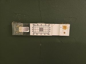 |
| Displacement Transducer | Converts movement into a variable electrical signal. |
| Extensometer | Measures changes in an object’s length, typically extension or elongation. |
| Pressure Cell | Converts pressure or stress into a measurable electrical unit. Typically installed to measure soil pressures on a structure (e.g., retaining wall, abutment, culvert). |
| Geophone | Used to record vibrations produced by seismic waves such as earthquakes or explosions. |
| Accelerometer | Records acceleration of an object. Typically used to monitor vibration. |
| Remote Monitoring Equipment |
Allows instrumentation to be read and data transmitted remotely. Typically installed at locations where extensive travel would be involved to read the instrumentation or where frequent readings are required over an extended period. 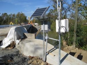 |
5.1 Pile and Drilled Shaft Test Programs
5.1.1 Dynamic Pile Testing
Dynamic testing of a pile is a method for evaluating the bearing capacity of a pile during the driving process. Instrumentation to measure acceleration and strain is placed on the pile head and evaluated in real-time during driving of the pile. In addition to the evaluation of pile bearing capacity, dynamic pile testing can provide information on the pile integrity (e.g. was the pile damaged during installation), performance and efficiency of the pile hammer, distribution of soil resistance on the shaft of the pile, end bearing resistance of the pile, and driving criteria for the remainder of the piles for the project or foundation unit. Since a pile’s capacity often increases with time after initial driving, a dynamic test can be performed at some time interval after installation to measure the pile setup. Pile capacity measured with dynamic load tests correlates well with static pile load test results. Using dynamic tests to verify pile capacity also allows more of the pile capacity to be utilized under LRFD Design Standards, resulting in fewer or shorter piles being required to support the structural loads.
5.1.2 Pile and Drilled Shaft Load Tests
Load tests on piles and drilled shafts are used to determine the response of a pile under an applied load. Data obtained from these tests is more accurate than data from engineering analyses and pile driving formulas. The tests are used to verify that the load capacity is greater than the nominal resistance used in the design. Use of load tests may allow a greater percentage of the ultimate pile capacity to be utilized to resist the applied loads, which in turn can reduce the number and lengths of pile required. Load tests are particularly useful in the following situations:
- Large projects with similar strata and pile types where large cost savings may be realized by reducing the number and length of piles.
- Unusual or variable site conditions where safe loading of the pile is uncertain.
- Design loads are significantly higher than typical design loads.
- Non-typical pile types or installation methods are to be used.
- Capacity predicted from pile driving formulas or dynamic pile testing during construction varies significantly from values used for design.
5.1.2.1 Static Load Tests
Static load tests measure the response of a pile or drilled shaft under an applied load. Static tests are the most accurate method for determining pile capacity, but they can be expensive and time-consuming to perform. A large reaction frame is needed to provide resistance to load the pile, and instrumentation is installed to measure the movement of and load placed on the pile. Loads placed on the pile are increased incrementally and the pile’s response is measured until it begins to plunge. Static load tests are often limited to large projects with similar subsurface conditions and pile types where large savings can be achieved by reducing the number and lengths of piles.
5.1.2.2 Dynamic Load Tests
Dynamic load testing is an alternative method of testing piles. Data from dynamic load testing correlates well with data collected from static load tests. The test involves applying a load to the pile over a very short period (less than one second) to create high strain in the pile or drilled shaft. The load can be applied by dropping a weight that impacts the pile head. It can also be applied by propelling a large weight upward through a small explosion, which is typically referred to as a Statnamic test. Statnamic tests can also be conducted in a horizontal direction to measure the lateral load capacity of piles or drilled shafts. These tests usually require much less time to perform than static load tests and do not require large reaction frames to load the pile or drilled shaft. As a result, dynamic load tests can be more convenient and economical than static pile load tests, especially for large-diameter piles or drilled shafts.
5.1.2.3 Bi-Directional Static Load Tests
Bi-directional static load tests involve embedding a hydraulic jack at a specified location within a pile or drilled shaft. The jack is often installed at the base of a pile or drilled shaft, but it can be placed at other locations within the pile or drilled shaft depending on anticipated loading conditions. When pressure is applied to the jack, it expands, loading the pile in two directions. Instrumentation placed within the pile or drilled shaft measures strains, stresses, and movement. The benefit of bi-directional testing is that it does not involve large reaction frames or weights to apply loads to test large-diameter piles or drilled shafts.
5.1.3 Pile and Drilled Shaft Integrity Testing
5.1.3.1 Crosshole Sonic Logging and Thermal Integrity Profiling
Crosshole sonic logging (CSL) is used to evaluate the structural integrity of a drilled shaft. Access tubes are tied to the shaft reinforcing cage. After concrete is poured in the shaft and has cured 3 – 7 days, a sound source and receiver are lowered into the tubes at regular intervals. Recorded data can identify areas of signal loss which represent areas of poor concrete, embedded anomalies, or other concrete defects. Because access tubes are tied to the cage, CSL only identifies defects within the cage diameter.
Thermal Integrity Profiling (TIP) can be used in addition to or in lieu of CSL. With this procedure, thermal wires are installed along the reinforcing cage. Concrete temperatures are measured within the shaft throughout the concrete hydration process. TIP analysis is performed at the peak temperature post-concrete placement. Locations in the shaft with cooler-than-average temperatures indicate a deficiency or defect may be present.
Defects within the shaft can be further explored after CSL or TIP testing by coring the shaft. Concrete samples can then be evaluated, and if deficiencies or defects are found they sometimes can be corrected by cleaning out and grouting the anomaly.
5.1.3.2 Pile Integrity Testing
Pile integrity testing (PIT) is a low-strain dynamic test used to assess the condition of piles or drilled shafts. It measures pile or shaft length and depth to anomalies. It is cost-effective, requires minimal preparation, and is not time-consuming. To conduct the test, a light impact is applied to a pile or shaft that produces a low strain. The compression wave travels down the pile, and anomalies or changes in cross section produce a wave reflection. While this test is typically performed prior to connecting the foundation to the structure, it can also be used to determine the lengths of piles embedded in structures.
5.2 Test Sections of Roadways
Constructing and evaluating a roadway test section can be effective for assessing the performance of previously untried construction methods or technologies. Test sections can be particularly useful under the following conditions:
- Large projects where the test section will be utilized to refine construction techniques, methodologies, and specifications.
- Projects where there is uncertainty about the performance of technologies with respect to site conditions.
- Projects where multiple technologies or techniques may be suitable and test sections are used to determine the most appropriate solution.
Test sections typically have instrumentation and monitoring devices installed to measure and evaluate performance. Test sections often can be incorporated into the final project. They require time and money to construct, and they must be built ahead of the project to allow time to monitor and evaluate results.
Many tools are available to conduct geotechnical investigations for design, construction, and maintenance of transportation facilities. The choice of tool depends on the problem to be solved and the geologic conditions of the project area. A geotechnical investigation that is thoughtfully planned and well-performed reduces the probability of cost overruns, claims, change orders, delays, construction problems, and maintenance issues.
Kentucky Transportation Cabinet (KYTC), Geotechnical Guidance Manual, Frankfort, KY, 2005. https://transportation.ky.gov/StructuralDesign/Interim%20Guidance%20Manual/Geotechnical.pdf
Loehr, J. Erik, A. Lutenegger, B. Rosenblad, and A. Boeckmann, Geotechnical Engineering Circular No. 5 – Geotechnical Site Characterization, FHWA NHI-16-072, Federal Highway Administration, Washington, D.C., 2016. https://www.fhwa.dot.gov/engineering/geotech/pubs/nhi16072.pdf
Mayne, P.W., B. R. Christopher, and J. DeJong, Subsurface Investigations (Geotechnical Site Characterization), FHWA NHI-01-031, Federal Highway Administration, Washington, D.C., 2002. https://www.fhwa.dot.gov/engineering/geotech/pubs/012546.pdf
Geotechnical Topics Knowledge Book:
Access the complete Knowledge Book here: Geotechnical Topics Knowledge Book
Next Article: Geotechnical Aspects of Construction
Previous Article: Kentucky Geohazards and Their Impacts to Highways and Bridges


