Search for articles or browse our knowledge portal by topic.
Utility Relocation Plans
Utility relocation plans are a critical compent of the utility relocation process.
This artice summarizes the 3WH series webinar for utility relocation plans and describes the what, why, who, and how of these plans. Webinar segments are linked in each section.

Utility relocation plans document utility relocation work necessary to complete a transportation project. Affected utility companies must submit detailed plans to KYTC that show the location of work needed to clear facilities from the highway contractor’s proposed work area. Once relocation work is complete, the functionality of relocated facilities must be similar to that of the original facilities.
At a minimum, utility relocation plans must include:
- Facilities to be relocated or removed, materials to be installed, materials to be transferred, and items to be left in place
- Specifications and standard drawings
Utility relocation plans should validate the cost estimate and KYTC cost participation.
In order to comply with KYTC utility relocation plan standards, the plans must:
- Be shown on the Cabinet’s plan sheets unless the work will occur outside the project limits
- Include KYTC cross sections or profile sheets showing utility facility crossings
- Identify the type of utility being relocated
- Identify the utility owner
- Use an appropriate scale and text size so they are readable when reduced to half scale
- Include utility company notes specific to the project or sheet
- Preferably be designed to the same scale as Cabinet plans
- Have a cut size of 36 inches by 22 inches
Utility relocation plans should depict the following items:
- Existing facilities
- Facilities to be removed, proposed relocations, proposed structures, materials to be installed, and materials to be transferred
- Items planned to be left in place
- For each proposed facility location, all changes in direction, junctions, or changes in grade
- Station and offset
- Coordinates or
- Offsets from the right of way (ROW)
- Existing and proposed ROW or easement lines
- Any betterment
Proposed facilities must be itemized on each sheet or a summary sheet to show estimated installation quantities.
Utility relocation plans should comply with the following delivery standards:
- KYTC must provide electronic plans in MicroStation or Cabinet-approved software.
- This minimizes the chance of data loss during conversion.
- Utility designers must develop relocation plans using MicroStation or Cabinet-approved software.
- If utility designers develop plans in another program, they assume liability for any data lost in the conversion process.
- Specifications and standard drawings shall be included, if needed.
23 CFR 645 Subpart A requires that utility relocation plans show:
- Location, length, size, capacity, type, class, operating conditions, and design features of existing, proposed, and temporary facilities
- Project number, plan scale and date, horizontal and vertical location of facilities
- ROW to be acquired from, by, or on behalf of the utility
- Work to be accomplished at the sole expense of the utility
- Appropriate notes or symbols
As stated in the Utilities and Rails Guidance Manual, relocation plans are required for both compensable and non-compensable utility relocations. These plans are essential for KYTC to:
- Avoid conflict with the road project
- Avoid other facility relocations
- Maintain compliance with utility accommodation policies
- Comply with KRS 177.035
- This statute requires that utilities submit a plan for facility relocation that includes plans, cost estimates, and specifies a reasonable calendar days for completion
*Note: KYTC’s utility accommodation policy, as stated in the Permits Manual, describes the conditions required to place utility facilities within the ROW limits of the Kentucky State Highway System.
Responsibilities for utility relocation are split between the utility company and KYTC (Table 1). The following people work on the utility relocation process:
- Utility Company
- Utility Manager
- Utility Designer
- District Utility section
- Utility Supervisor (US)
- Utility Agent (UA)
- Central Office Utilities Branch
- Area Coordinator (AC)
- Utility & Rail Branch Manager (UBM)
Table 1: Work Assignments for KYTC and Utility Company Staff
| Table 1:Work Assignments for KYTC and Utility Company Staff | |
|---|---|
| Personnel | Responsibilities |
| Utility Company Staff |
|
| KYTC District Utility Section |
|
| KYTC Central Office Utilities Branch |
|
5.1 Plan Review Process
The review process for utility relocation should include the following key elements:
– Review the plans
– Address questions, errors, or omissions
– Ensure final relocation plans are posted for record and approved in KURTS
– Confirm a validated estimate is approved
– Verify the utility relocation agreement is written, signed, and executed
– Ensure construction work is completed and that facilities no longer conflict with the project
5.2 Utility Plan Production
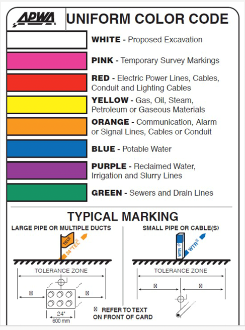
KYTC’s CADD procedures and standards for utility relocation plans adopt the American Public Works Association (APWA) color codes for marking underground utilities (Figure 1).

Red Flag
5.3 Highway Plan Set
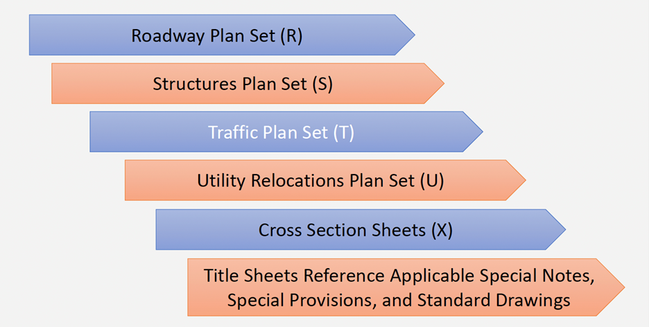
Because multiple plan sets comprise a full highway plan set (Figure 2), when plan sets are developed cross-discipline coordination is imperative. Individual plan sets must be reviewed to verify that utility conflicts are mitigated and depicted correctly.

Figure 2: Elements of a Full Highway Plan Set
5.4 Placement of Utilities in the Right of Way
The location of utility facilities in the ROW must adhere the Utility Accommodation Policy (UAP) outlined in the Permits Manual. Here are some general placement criteria:
- If facilities will be located within the public ROW, they cannot impede the use and function of the road and its appurtenances.
- Longitudinal facilities parallel roadways must be adequately distanced from traveled pathways and ROW features.
- Facility crossings must be perpendicular to the highway alignment. Underground facilities (e.g., electrical, cable, phone, fiber optic) should be encased in a conduit.
- On fully controlled access highways, the minimum vertical clearance for overhead utility crossings is 24 ft.
- On highways that lack full access control, the minimum vertical clearance for overhead utility crossings is 18 ft.
When relocating utility features, consider safety features such as the clear zone and sight distance. The clear zone is the unobstructed, traversable area provided beyond the edge of the through traveled way for the recovery of errant vehicles. Obstacles should not be placed in the clear zone when possible. Sight distance is the length of highway that is visible ahead of the driver. Features that restrict the driver’s sight distance should be avoided as well. Utility accommodation features that could impact the clear zone or affect site distance include poles, hydrants, regulators, junctions, cabinets, stations, and other structure. See KYTC’s Highway Design Guidance Manual and AASHTO’s Roadside Design Guide for more information on clear zones and sight distance.
Aesthetics must also be considered when placing utilities along the roadway. The size and type of utilities in scenic areas can materially alter the visual quality of the roadside. Examples of scenic areas that may require aesthetic considerations include:
- Scenic strips
- Overlooks
- Rest areas
- Recreation areas
- Public parks
- Historic sites
5.5 Effective Utility Plans
Effective utility plans must adhere to criteria described in previous sections. Video 5-5 illustrates the correct application of these criteria by presenting critiques of three different utility plans.
Video 6 is a question-and-answer session from the July 2023 webinar. Presenters received one question, about exceptions to utility accommodation policies. Details about exceptions are summarized below.
- Exceptions to utility accommodation policies can be made.
- On interstates, requests for exceptions must be submitted to the State Highway Engineer’s Office and
- For controlled access routes, requests for exceptions must be submitted to the State Highway Engineer’s Office.
- A standard memo is used to request exceptions. When submitting a request, include the portion of the plan sheet that depicts where an exception is needed.
- On routes without access control, a formal request for an exception does not have to be submitted. The AC, US, and project team in the district office decide how to proceed. Thoroughly document the decision-making process and justification for the choice made.

