
Search for articles or browse our knowledge portal by topic.
Landslides
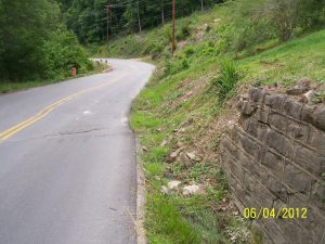
A slide is the downslope movement of a mass of soil, rock, or soil/rock mixture along a thin, well-defined shear plane. Slope movements occur when forces that resist slope movement are less than the forces that propel materials downslope. Resisting forces are usually attributed to the strength of soil or rock but can include externally applied forces such as walls or tie backs. Driving forces are generally gravity-type loads (i.e., weight of the soil or rock mass) but can also include externally applied loads (e.g., equipment, buildings, stockpiles). Severe slope failures can cause enormous economic losses, traffic disruptions, and even casualties. The costs to repair or mitigate slope failures can greatly exceed the expense of properly constructing and maintaining slopes. Table 1 reviews different types of rock and soil movement.
Figure 1 Pavement Failure Triggered by a Slide

| Table 1 Forms of Rock and Soil Movement | |
|---|---|
| Movement Type | Description |
| Fall | Downward movement of rock or soil through the air by falling, bouncing, or rolling. The most common type of mass movement on slopes ranging from 45 to 90 degrees. |
| Topple | The forward rotation out of a slope of a mass of soil or rock around a point or axis below the center of gravity of the displaced mass. |
| Slide | Downslope movement of a soil or rock mass that occurs along the surface of a rupture or along a relatively thin zone of intense shear. |
| Flow | A slope failure that flows like liquid due to the presence of water. Flow (or mudflow) characteristics are influenced by the amount of water in the soil and the soil’s behavior under changing water conditions. |
| Spread | A landslide that involves the extension of cohesive or hard rock masses due to the lateral movement of softer and weaker underlying material. |
| Settlement | Settlement of an embankment or sidehill fill slope combines the settlement of (1) the embankment fill and (2) the foundation on which it rests. If the slope is constructed over a weak foundation, settlement may be substantial. Settlement typically occurs over an extended period of time. |
| Creep | Incremental downslope movement that takes place slowly (< 1 ft per decade). Results from cyclical freezing and thawing or wetting and drying, burrowing by animals, and downhill displacement of material by uprooted trees. For cohesive materials (clay and silt), tension cracks can form as soil moves downhill. Over time creep can lead to faster and more extensive soil movements. |
Figures 2 – 4 illustrate several types of rock and soil movement.
Figure 2 Rockfalls and Topples

Figure 3 Slide

Figure 4 Settlement

This article focuses primarily on landslides involving soil slopes. Slope movements involving rock cuts and slopes are discussed in the article, Rock Slopes and Rockfalls. Landslides involving soils slopes are classified into four general categories (Table 2).
| Table 2 Landslide Classifications | |
|---|---|
| Category | Description |
| Wedge Slide | A translational slide in which a wedge-shaped mass of rock moves downward along the intersection of two planar surfaces. |
| Rotational Slide | Outward and downward movement of the soil mass along a concave-upward failure surface. Before failure, cracking can be seen at the head of the failing slide. They can consist of a single slump or show multiple nested failure surfaces. |
| Block Slide | A translational slide in which a single block of material slides downslope as a coherent mass. |
| Compound Slide | Any combination of wedge, rotational, and block slides. |
Figures 5 – 7 illustrate each of these types of slides.
Figure 5 Wedge Slide

Figure 6 Rotational Slide

Figure 7 Block Slide

Slide magnitude, type, cause, and location strongly influence remediation and repair options. The causes of a landslide should be evaluated to determine the most appropriate corrective action. In some cases, selecting the wrong type of corrective action can aggravate slope movement. Table 3 lists the corrective actions most often used for small, medium, and large slides.
| Table 3 Corrective Actions Used to Remediate Slides | ||
|---|---|---|
| Slide Type | Height of Slope Failure | Corrective Action |
| Small | < 20 ft | Repair by maintenance crews if budget and crew availability allow |
| Medium | 20 – 40 ft | Decision to repair with maintenance crews or by outside contractors is made on a case-by-case basis |
| Large | > 40 ft | Special remediation performed by outside contractors |
Several main factors contribute to slope instability and landslides. These include:
- Water — Water is the number one factor in slope failures. Water raises the groundwater elevation within a soil mass, adding weight to the slide while reducing soil strength. Typical water-related issues that contribute to landslides are:
- Intense or prolonged rainfall and snowmelt.
- Natural springs — construction of new fills may block the outlets for springs and cause groundwater elevations to rise in the slope.
- Improper surface drainage.
- Water standing in ditches or nearby ponds.
- Clogged or damaged cross drains and culverts.
- Water discharged onto slopes from pavement runoff or downspouts.
- Rapid drops in water levels from adjacent streams, lakes, or ponds. Bridge approach embankments crossing bodies of water are examples of slopes that can be impacted by fluctuating water elevations.
- Geology — The types of rock and soil that compose a slope is a major contributor to landslides. Some soil and rock materials are weaker than others and are more prone to slope movements.
- Slope angle and terrain — Steep slopes generally result in greater driving forces. These higher forces due to gravity exceed the ability of the soil mass to support itself and result in slope movement. Steep slopes can be naturally occurring or can be constructed through cuts or fills.
- Erosion — Erosion from streams or improper surface drainage can remove soil material and supporting vegetation from the slope and allow a slide to occur.
- Improper initial construction — Slope movements can sometimes be attributed to initial construction activities and failure to follow plans and specifications. These issues include:
- Failure to properly compact fill materials, which results in lower soil strengths, a higher probability of water saturating the soil, and excessive settlement.
- Slopes constructed too steep or at an angle other than what was shown on the plans.
- Failure to properly clear, grub, and bench natural ground prior to fill placement.
- Use of weaker fill materials than were specified in the plans.
- Stockpiling materials on top of a slope or cutting out the bottom of a slope.
- Human Activities — Human activities next to a slope can also impact slope movements. These include:
- Construction of buildings or building seats next to a slope —Buildings, storage facilities, or other construction located near the top of a slope can add weight to the slide. Cutting out the bottom or toe of a slope to place a building or building seat removes material that supports the slope.
- Vegetation removal — Vegetation and its associated root mass stabilize slopes, reduce infiltration of precipitation, and remove groundwater. Removing vegetation also increases the likelihood of erosion on a slope.
- Discharge of drainage from downspouts, parking lots, and other constructed features — Discharge of drainage onto a slope can increase the groundwater level and saturation of the soil mass, thus adding weight to the slide and reducing soil strength. It can also erode a slope.
- Maintenance Activities — While maintenance activities can be very helpful in preventing slope movements, they can trigger or accelerate slope movements if done improperly. Examples include:
- Failure to maintain ditches, cross drains, and culverts results in ponding water that saturates a slope.
- Excessive cleaning or over excavation of ditches, which can remove supporting materials at the bottom of a slope.
- Casting waste soil and rock over a slope, which can add weight to a slide.
- Excessive patching of pavement — Patching pavement is necessary to maintain traffic, however, asphalt weighs more than soil. Frequent patching can add several feet of asphalt pavement, which adds weight to a slide and can accelerate soil movement.
Other characteristics are correlated with movement or vulnerability to movement in cuts and fills:
- Thin soil cover over bedrock can be unstable, easily saturated, and may creep.
- Sidehill cut and fill sections are particularly prone to instability. The toe of the cut slope on the uphill side is prone to erosion and loss of toe support. Improper benching and drainage under fill sections can provide a failure plane along which the fill can slide.
Figure 8 Profile View of a Cut and Fill Section

- Large or high fills – Fills over 20 feet in height are generally more susceptible to failure and require careful evaluation before construction.
- Soft or saturated foundation soils may fail from embankment loads.
Engineers and technicians can visually inspect slopes and adjacent infrastructure to determine points of instability. Table 9 lists visual indicators of slope instability for different elements of the built environment.
| Table 4 Visual Signs of Slope Instability | |
|---|---|
| Element | Visual Indicators of Slope Instability |
| Bridges | • Abutment or Pier Tilting • Tilted bearings that are inconsistent with a structure’s typical thermal movement • Abutment moving toward deck beams |
 |
|
| • Settlement of approach slabs • Exposed piles • Closed, twisted, or excessively open bridge joints | |
 |
|
| Retaining Walls | • Overturned or tilted • Out-of-alignment wall facing • Cracking • Settlement or differential movement |
 |
|
| Buildings | • Foundation cracks • Cracks in masonry walls • Elevation changes • Differential settlement |
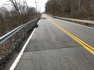
| Roads | • Tension cracks |
 |
|
| • Sunken guardrails | |
 |
|
| • Dips in grade (downhill side of roadway) • Bulges in grade (uphill side of roadway) • Shifts in roadway alignment — A snake-like alignment not due to the design or original construction may indicate past movement. • Poor drainage | |
 |
|
| • Erosion • Leaning utility poles and trees | |
 |
|
KYTC stabilizes and repairs slopes to restore highway sections to an acceptable condition. Methods for stabilizing and repairing slope failures generally fall into five categories:
- Modify slope profile
- Increase the soil’s shear strength
- Control the surface and subsurface drainage
- Retain the slope using a wall, berm, or other type of structure
- Relocate to avoid the problem
Methods are selected based on many factors, and slope failures must be examined individually to determine the most economical and appropriate corrective action. Methods used to repair and/or stabilize soil slopes are described below.
4.1 Slope Flattening, Berms, and Slope Height Reductions
Because the steepness of a slope and slope height are major factors controlling slope stability, flattening slopes and reducing slope height of cuts and fills are common methods of repairing slopes if adequate right of way, fill materials, or waste areas for excavated materials are available. Berms are also an effective method of slope flattening using a stepped slope. Berms help resist the forces driving slope movement and effectively flatten the slope. Additional embankment or berms may be constructed out of crushed stone or soil.
Figure 9 Flattened Soil Slope with Berm

Often, drainage blankets or another method of groundwater control is included with these types of corrections. Care must be taken that the additional fill materials do not create a dam-like effect and increase the elevation of groundwater within the slopes.
4.2 Excavation and Replacement
A common method of slide repair is excavating failed material and replacing it with a stronger material, such as crushed stone (sizes No. 1, 2, 23, or 3). Crushed stone from roadway excavation can be used if it is relatively free of fine-grained material. Crushed stone is stronger than excavated soil, lets groundwater freely drain, and typically has less weight than saturated soil. A geotextile is typically placed as a separator between the remaining soil slope and crushed stone.
Figure 10 Excavation and Replacement

This corrective action can be combined with a shear key, where a portion of the soil below the failure surface is excavated and replaced with crushed stone. Intercepting the failure surface with crushed stone increases resistance to sliding.
Figure 11 Excavate and Replace into Bedrock with a Shear Key

Excavation and replacement can be used for slides of many different magnitudes. In most cases a careful evaluation of the slide type and location of the failure surface is needed to make sure the proper amount of excavation and replacement occurs. Excavation and replacement must be done in a timely manner as the excavation itself could trigger additional slope movement. If possible, any excavation should be performed during dry seasons when precipitation and groundwater elevations are low.
Figure 12 Slope Repaired by Excavating Failed Material and Replacing It with Crushed Stone

4.3 Drainage Improvements
Although drainage and control of groundwater is a consideration when choosing a slope repair method, sometimes simply improving drainage and lowering groundwater elevations within the slope are sufficient to stabilize a slide. Eliminating standing water that infiltrates and saturates the soil, whether in ditches or ponds above the slope, can slow down and sometimes stabilize slides. Maintaining positive drainage in ditches, cross drains, and culverts is essential for reducing the amount of infiltration into a slope. Controlling surface drainage off pavements is also important to reduce erosion and minimize the saturation of slopes.
Horizontal drains are a method of removing groundwater within a slide mass. A nearly horizontal drainage pipe is placed into a drilled hole that extends from the toe of the slope a sufficient distance into the slope to intercept the groundwater source. By reducing the groundwater in the soil mass, the slide may be stabilized. Horizontal drains are occasionally combined with other repair methods to drain groundwater out of a slope.
Figure 13 Horizontal Drains

Pavement drainage has the potential to saturate slopes and to cause erosion. Often, this initially creates small, shallow slips in the downhill slope that will enlarge over time. Controlling surface drainage from pavement with asphalt curbs and flumes can prevent or correct this situation.
4.4 Retaining Structures
Retaining structures can be used to remediate slope movements. Common types of retaining structures are described below.
4.4.1 Railroad Rails and Cribbing
Railroad rails are installed in a row or rows of predrilled vertical holes backfilled with aggregate or grout after rail has been placed. They are typically used to remediate landslides on sidehill cut and fill sections in hilly terrain. Often a district may have a price contract that covers rail installation.
- Rails are installed parallel to the road near the shoulder (Figure 14).
- Care must be taken to protect a retained soil mass from erosion after the soil slope moves downslope of the rail pile wall.
- Used guardrail is often incorporated as lagging to prevent the erosion of retained soil (Figure 15).
- Empirical design charts and installation details are available in KYTC’s Active Sepia 25. (Coming Soon)
- Rails are supplied in 39-foot sections.
- Design guidelines require that 1/3 of the rail’s total length be embedded in bedrock or below the failure plane (Figure 16).
- Rails should only be used where the failure plane’s depth is less than 21 feet.
Figure 14 Double Row of Railroad Rails Installed Parallel to Roadway

Figure 15 Used Guardrail is Often Incorporated as Lagging to Prevent Erosion of a Retained Soil Mass

Figure 16 Typical Cross Section of Roadway Repairs Using Rails to Remediate a Landslide

4.4.2 Soil Nailing
Soil nailing is an in-situ soil reinforcement technique where passive inclusions (soil nails) are placed into the natural ground at relatively close spacing (3 to 5 feet) to increase soil mass strength.
Installation entails drilling to a prescribed depth, inserting a steel soil nail, and grouting the nail in place. Ideally, the soil nails extend through the sliding mass into stable material below the sliding plane. In the past, soils nails were shot into the ground using a launcher, but this is no longer a recommended practice. A drainage system is installed on the exposed face. Bearing plates are then fixed to the heads of soil nails. This installation process is repeated until the design wall depth is reached. Finished soil nails create a zone of reinforced ground. A facing is then placed to prevent raveling and erosion of soils between the nails. Soil nails are used often in mountainous areas where terrain limits construction options. They can also be used to stabilize fills, steepen slopes, or create retaining walls. Districts may have a price contract in place to install soil nails.
Figure 17 Installing Soil Nails

Soil nailing carries the following advantages:
- May be more cost-effective than alternative technologies
- Quick construction
- Can be constructed with limited headroom and limited right of way
- Can withstand large deformations
- Easily monitored and tested
The following geologic criteria should be considered when deciding whether soil nails are appropriate:
- Soil nailing works well in sands, gravels, silts, and clays.
- Soils with large boulders or cobbles are not suitable for launched soil nails.
- Soils that are corrosive or prone to liquefaction or collapse when water is present are not suitable for soil nails.
- A high groundwater table should be drained if the forces are too great. Water decreases slope stability.
- Soil nails should extend past the sliding plane into stable material.
- A stream or body of water at the toe of the repair can degrade long term performance by undercutting or destabilizing material beneath the repair.
Shotcrete facings are typical with soil nails, but another type of face that can be used is geosynthetically confined soil (GCS) walls.
4.4.2.1 Soil Nails with Shotcrete Wall
Soil nails are used in combination with a steel grid cover and shotcrete. The soil nail, grid cover, and shotcrete function as a coherent mass and are strong enough to resist the overburden pressure of the surrounding soil mass as well as any surcharge pressure. Typically, reinforcing wire is secured to nail heads before applying 3–4 inches of sprayed-on shotcrete. The appearance of permanent walls can be improved by imprinting a texture or pattern, stacking stone or block along their faces, or using aesthetic landscaping.
Figure 18 Soil Nail Wall with Shotcrete Face Above Grade

4.4.3 Soil Nails with Geosynthetically Confined Soil (GCS) Wall
GCS wall may be used in conjunction with soil nails and/or shotcrete to create a wider platform or to construct a small box or abutment wall. This wall may consist of a standard, split-faced concrete masonry unit, road base backfill, and a woven polypropylene geosynthetic fabric placed between each block.
Figure 19 Soil Nail Wall with Masonry GCS Face and Riprap

4.4.4 Gabions
Gabion walls are principally used to stabilize the soil behind a wall; however, they can also serve as cover walls. A wall is made from gabion baskets that are stacked in one or more rows, depending on the wall height. Baskets assume the form of a cage and are enclosed on all sides. They are made of galvanized hexagonal meshes, with crushed stone placed inside the baskets. Refer to Standard Drawing RGX050 (Type in drawing # into table. Do not include dashes or spaces) for gabion wall construction details.
- Retaining structures are formed by stacking gabion baskets in a proper schedule.
- Gabion walls permit the free flow of water downslope. A geotextile is usually placed between the gabions and the retained soil to prevent soil migration through the crushed stone in baskets.
- Most gabion walls do not require a concrete foundation.
- Cages are available in a variety of sizes, which allows for flexibility in construction.
- They can be relatively cheap and inexpensive to install. Often maintenance crews can handle installation.
- Gabion installation is somewhat labor intensive. Baskets are hand tied together; some placement by hand is needed for the rock fill in baskets.
Figure 20 Gabion Baskets

4.4.5 Tieback Walls
Tieback walls are used to hold back rock and soils on a range of sites. They are typically constructed with vertical steel members and timber or concrete lagging. These walls are tied back into the slope using an anchoring system made of steel tendons, cable anchors, strand anchors, deadman anchors, or many other materials. Typically, tiebacks are drilled into soil or bedrock using a small-diameter shaft and installed at an angle of 15–45 degrees. Anchors provide a restraining force to counteract soil movement. Often a cast-in-place concrete facing is used to provide a more durable and aesthetic facing on the wall. Tieback walls can also be fabricated with lock block walls, mechanically stabilized earth (MSE) retaining walls, gabion walls, sheet pile walls, or many other hybrid materials. If a permanent facing is not placed on a tieback wall, periodic inspections and maintenance must be performed as the wall could undergo corrosion from road salts, deterioration of the timber lagging, and vegetation growth through the wall.
Figure 21 Tieback Wall

4.4.6 Concrete-Filled Bags
Concrete-filled bags offer an erosion-control alternative to installing large riprap, which can be expensive and labor intensive. Installing bags is inexpensive because neither heavy equipment nor significant labor are needed. Reinforcing dowels can be inserted into the completed block to interlock with the next layer. Fabric-formed concrete bags support custom design to ensure the most stable protection and repair of waterfront applications. Bags must be set on a solid foundation to perform properly. They should not be used as retaining walls without proper investigation and design.
Figure 22 Concrete Bag Wall and Scour Protection

4.4.7 Other Wall Types
With proper design, other wall types can be integrated into a repair plan for slides. These include standard gravity walls (Standard Drawings BGX023 and BGX024), cast-in-place concrete walls, MSE walls, sheet pile walls, and proprietary wall types (e.g., approved large concrete block walls).
Figure 23 Standard Gravity Wall Used in a Rock Cut Where Expected Bedrock Was Missing. Note: The wall was used to retain overburden soils and avoid taking more right of way.

Figure 24 Sheet Pile Wall

Figure 25 Large Block Retaining Wall

4.4.7 Geosynthetic Reinforcement
Geosynthetics can be used to reinforce and strengthen slopes. These inclusions allow for the construction of steeper slopes than would be possible with unreinforced soils. High-strength geotextiles or geogrids can be placed in layers within the soil, typically at 2-to-3-foot spacings. These can be used in initial slope construction. A failed soil mass can also be excavated and reconstructed with these inclusions. As with other types of repairs, controlling drainage and groundwater is critical. Careful design work is needed to determine the proper length, spacing, and strength of the geosynthetic.
4.4.8 Lightweight Fill
Because gravity and the weight of soil create the forces that propel a slide, reducing the weight of soil is an option for stabilizing slope movement. Soil material at the top of a sliding mass is removed and replaced with lightweight materials. Materials used for this purpose include:
- Styrofoam blocks
- Lightweight cellular concrete
- Sawdust
- Shredded tires
- Lightweight aggregate
These materials have drawbacks. Styrofoam blocks are vulnerable to fuel spills as they disintegrate when exposed to fuel. Sawdust and shredded tires tend to be very compressible under load, can be subject to fires, and could result in environmental issues if placed improperly. Lightweight cellular concrete and aggregates are stable materials but can be expensive.
4.4.9 Avoidance of the slide area
Sometimes it is best to simply avoid the slide area. This might involve moving the roadway alignment or changing roadway grades. This generally occurs for massive landslides where the cost of repairing a slide is exorbitant, large amounts of right of way are needed, and repair costs exceed the costs of roadway relocation.
4.5 Repair Concerns and Considerations
Sometimes a combination of repair methods is used to remediate a slide, such as using a soil nail wall with horizontal drains, combining slope flattening with a drainage blanket or French drain, excavating and replacing with a small wall to avoid right-of-way or utility impacts, or a blend of other methods. To determine the best repair method, consider the following issues:
- Right-of-way and utility impacts
- Traffic impacts
- Groundwater sources and elevations
- Geology and terrain
- Environmental issues
- Availability of resources (e.g., labor, materials)
- Availability of space and access for construction equipment
- Funding availability
- Other items specific to the slide and situation
4.6 Role of Maintenance
Generally, the role of maintenance forces is to ensure safe passage for motorists and keep roads open when possible. Normal maintenance activities can reduce the likelihood of slope failures:
- Conduct routine slope maintenance
- Monitor and report slope deterioration
- Restore slopes impacted by small slide(s)
- Clean ditches, cross drains, pipes, and culverts; maintain positive drainage in them
- Repair slope and stream erosion
- Seal pavement cracks
- Remove soil, rock, and other debris from roadways
- Minor pavement patching
- Implement temporary measures to slow or halt slope movement
If extraordinary maintenance activities are needed, it may be necessary to request assistance with repairs. Examples of extraordinary maintenance activities include:
- Large costs required to halt or slow down slope movement to keep roadway open.
- Frequent maintenance required at a location.
- Continuous patching to maintain grade or a driving surface.
- Asphalt weighs more than soil. Frequent patching significantly thickens asphalt, which can accelerate slope movement.
- Clearing large debris, rocks, and other materials.
4.7 Role of Section Engineer
The Section Engineer is responsible for identifying potential issues that may occur along a section of roadway in their jurisdiction. This includes facilities open to traffic as well as those under construction. The Section Engineer needs to identify potential landslides and rockfalls as well as:
- Facilitate the initial response to road closures and hazards or to construction activities.
- Document the extent of the current area of concern.
- Evaluate information on past repairs/remediation.
- Identify drainage/sources of water infiltration.
- Identify potential utilities or right of way that may be impacted.
- Work with Central Office Maintenance or Central Office Construction as necessary to determine the best course of action.
- Local involvement only (repair/remediation made with local staff or contractors).
- Utilize statewide price contract for standard repairs.
- Contact Geotechnical Branch for detailed analysis and design.
- Help obtain survey information to facilitate repair plan development – Section 200 of the Geotechnical Guidance Manual (GT-1) lists items needed to evaluate and develop plans.
- Implement and oversee construction of repair options.
4.8 Role of Central Office: Maintenance–Roadway Maintenance Branch and/or Construction Field Liaison
The Central Office Roadway Maintenance Branch and/or Construction Field Liaison:
- Helps identify the scope and magnitude of the slide area.
- Assists with potential funding sources for large remediation repairs and/or analysis.
- Assists with utilizing price contract repairs and remediation.
- Provide additional expertise when reviewing repair options.
4.9 Role of Geotechnical Branch
The Geotechnical Branch:
- Provides review and expertise to identify the cause(s) of slides and assists with further investigation.
- Maintains data on landslides and rockfalls across the state, including their locations, previous site visits, and previous reports or repair recommendations (i.e., Geotechnical Database and Data Collector application).
- Manages drilling or forensic evaluations.
- Develops remediation and repair plans for slides.
- Monitors ongoing problem areas with in-situ instrumentation.
4.10 Funding Sources for Slide Repairs
Identifying funding for slope maintenance and landslide repairs can be challenging. Because landslides are usually tied to weather or unforeseen events, planning for them in advance is typically not possible. Key funding sources include:
- Roadway Maintenance Funds — Funds are allocated yearly to perform regular maintenance on state highways. Regular maintenance activities are common methods for dealing with small or medium landslides. These activities include ditching and drainage maintenance, debris removal, and erosion repairs. On occasion, some repairs like railroad rails and soil nail walls can fit under this item.
- Six Year Highway Plan (SYP) Z-Various Funding — KYTC often sets aside funding in the SYP to provide flexibility in addressing unanticipated events, such as landslides and rockfalls. Some items in the SYP may target landslides and rockfalls, or discretionary funding may be set up for any type of emergency repairs. Funding can be sourced from the state or federal governments, and as such may have restrictions on its use.
- Inclusion in a Six Year Plan (SYP) Project — A landslide or rockfall within the project limits of a SYP Project may be eligible for repair under that project if the scope and budget allow. If slide repair is not time sensitive, it is theoretically possible to include a project in the SYP to repair the slide. Often, repairing a landslide or rockfall is time sensitive and cannot wait until a project is let for construction or for funding to be approved through the SYP process.
- Other funding — Occasionally funding comes from non-traditional sources (e.g., FEMA or Federal Emergency Relief (ER) in response to a disaster or emergency event). Other government agencies may provide funding or grants for items like infrastructure resiliency, dam repairs, and other tasks. These funds often carry restrictions and require approvals that hamper their use.
- Additional information about funding sources can be found in the following articles: Disaster-Aid Funding Knowledge Book, Department of Rural and Municipal Aid, and Understanding the KYTC Budget and Highway Plan.
The KTC Geotechnical Database provides a repository of past geotechnical investigations, including drilling, geotechnical reports, and historical landslides and rockfalls.
Information on items related to roadside maintenance or drainage activities can be obtained from KYTC’s Operations Management System.
District Offices may have price contracts in place for installation of railroad rails, installation of soil nails, and other typical landslide repair options. These contracts give maintenance personnel another method to address and repair landslides.
Turner, A. Keith, and Schuster, Robert L., Editors, Landslides: Investigation and Mitigation, Special Report 247, Transportation Research Board, National Research Council, National Academy Press, Washington, D.C., 1996, 673 p.
Geotechnical Topics Knowledge Book:
Access the complete Knowledge Book here: Geotechnical Topics Knowledge Book
Next Article: Rock Slopes and Rockfalls
Previous Article: Geotechnical Investigations – Where to Begin and How to Proceed